Chapter 1. setting up – IAI America S-SEL-E User Manual
Page 17
Page 15
2.
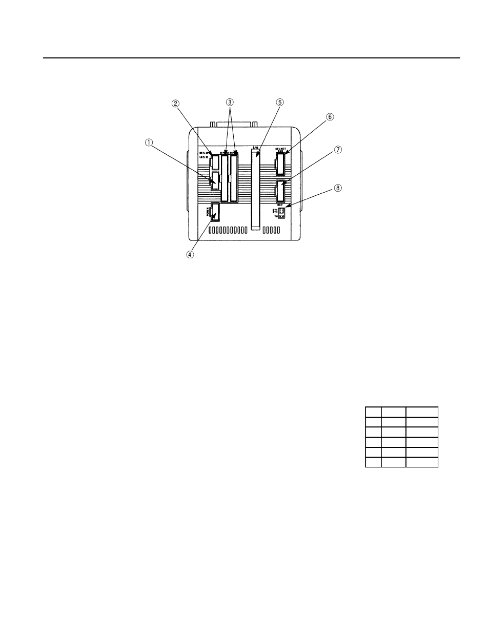
Controller Bottom View
Chapter 1.
Setting Up
LS
(Limit Switch Connector) (Option)
5 pins, limit switch connector (Model: Nippon Molex 53258-0520)
BK
(Brake Connector) (Option)
4 pins, brake output connector to a brake unit (option) (Model: Nippon Molex
53258-0420)
M·PG
(Servo Motor Output/Encoder Input Connector)
14 pins, servo motor output/encoder input combined type connector (Axis 1 is
on the left and Axis 2 is on the right) (Model: Nippon Molex 53258-1420)
Power
(Power Cable Connector)
3 pins, AC power supply cable connector
Since Type E and Type G are designed to be mounted inside of a controller
panel, no plug is provided for the power cable on the other end of the controller.
(Terminal Type) (Model: Nippon Molex 53265-0320)
I/O
(I/O Connector)
50 pins, external I/O connector. This is used for Type E and Type G (2 axis)
up to 100W only. For other models, it is attached to the I/O Unit Box.
(Model: Sumitomo 3M 7950-6500FL)
SEL NET
(Optional SEL Network Connector)
SEL. Network transmission connector. (Model: Nippon Molex 53259-0620)
ST1
Emergency Stop release jumper post. Refer to "Supplement 6. Emergency Stop".
*Power Cable, Terminal
No.
Color
Signal
1
Black
AC117V
2
---
---
3
White
AC117V
4
---
---
5
Green
FG