Chapter 1. setting up, Part 7 system setup – IAI America S-SEL-E User Manual
Page 30
Page 28
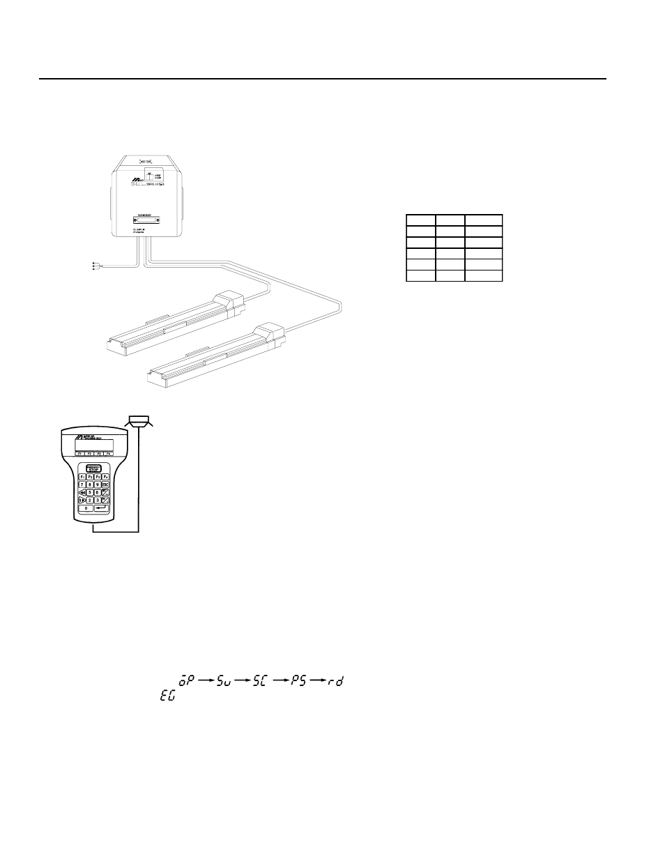
Connect controller and actuator cables. Use only IA supplied cables. These cables include:
a. Motor cable
b. Encoder cable
c. Teaching pendant cable
d. Brake cable (optional)
e. Limit switch cable (optional)
Connect the power cord.
The CODE display shows
in sequence. The Super SEL controller is ready to operate.
If the CODE display is release the Emergency Stop input.
Note: The Emergency Stop is normally closed (b contact point input). In order to release the emergency stop, short the jumper
post (ST1) at the bottom of the controller CPU UNIT or CPU SERVO UNIT with the jumper pin. Refer to Supplement
6 for the actual procedure.
Part 7
System Setup
1.
Connecting the IA Controller and Actuator
Chapter 1.
Setting Up
Teaching Pendant
* Since Type E and Type G Controllers are designed to be mounted
inside of a control panel, no plug is provided for the power cable
on the other end of the controller.
*Power Cable·Terminal
N o.
C olor
S ignal
1
B lack
A C117V
2
---
---
3
W hite
A C117V
4
---
---
5
G reen
FG