Chapter 1. setting up – IAI America S-SEL-E User Manual
Page 39
Page 34
Chapter 1.
Setting Up
Nippon Molex
53258-0420
(4P) (Body side)
51067-0500
Housing (4P)
50217-8100
x 4 Terminal
Nippon Molex
53258-1420
(14P) (Body side)
51067-1400
Housing (14P)
50217-8100
x 14 Terminal
X (1) Axis
X (1) Axis
Nippon Molex
53265-0320
(3P) (Body side)
51067-0500
Housing (5P)
50217-8100
x 3 Terminal
Nippon Molex
53258-0520
(5P) (Body side)
51067-0500
Housing (5P)
50217-8100
x 5 Terminal
5.
Connector Pin Assignment
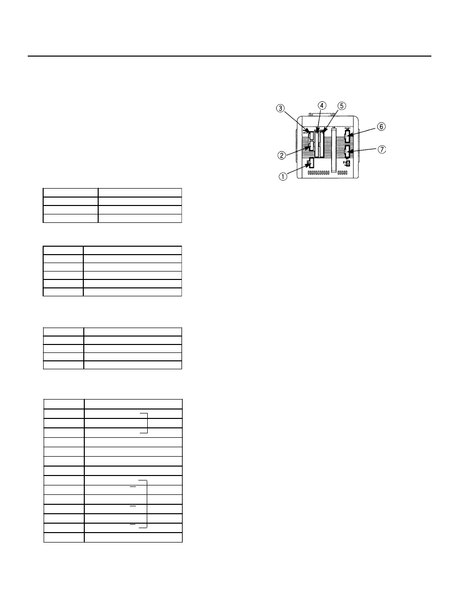
The bottom view of the Super SEL Type E/G on the left shows the placement of the connectors. Please refer to Page 29 and
31 for the I/O connector and the I/O wiring (including the I/O expansion).
The connector pin assignment for the other parts are shown below.
(1) AC100W 2-Axis specifications
M·PG Connector (Motor/Encoder Signal)
BK Connector (Option)
* The Emergency Stop is normally open.
LS Connector (Option)
Power Supply Connector
P in N o .
S ig n a l
1
A C 11 7 V
3
A C 11 7 V
5
F G
P in N o .
S ig n a l
1
P 2 4 V
2
N
3
X L S
4
Y L S
5
E M G s to p c o n ta c t p o in t in p u t*
P in N o .
S ig n a l
1
6 0 V
2
G D
3
X B K
4
Y B K
Pin No.
Signal
1
U
2
V
3
W
4
NC
5
FG
6
PV5
7
GD
8
A
9
A
10
B
11
B
12
Z
13
Z
14
FG