Chapter 1. setting up chapter 1. setting up, I/o wiring diagram – IAI America S-SEL-E User Manual
Page 32
Page 30
Chapter 1.
Setting Up
Chapter 1.
Setting Up
3.
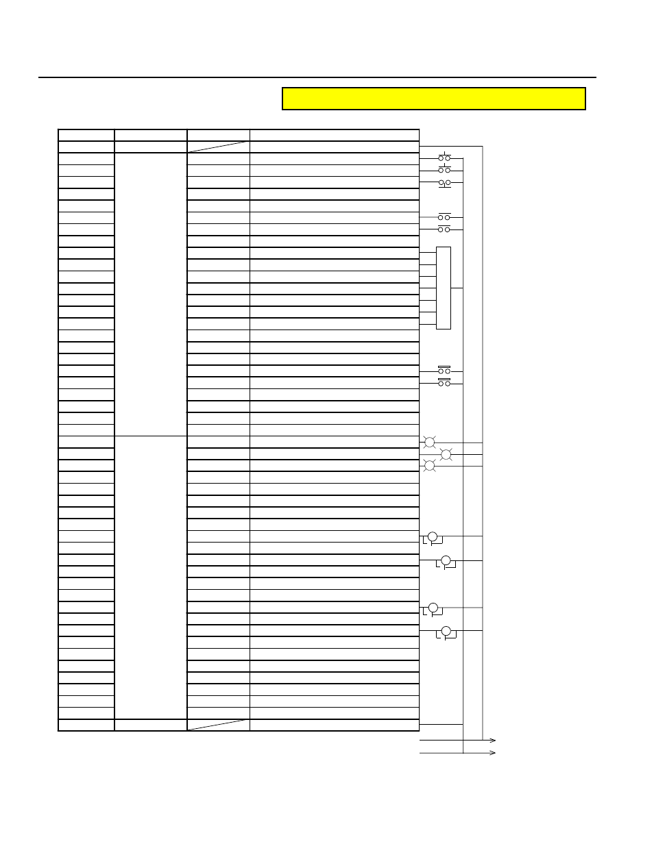
I/O Wiring Diagram
Standard I/O
(NPN - Sinking)
0
P24
•
Note: The same cable colors
are used for the standard
cables and the expan-
sion cables.
*
Standard I/O Pin No.3A
(Port No.003), and Pin
No.3B(Port No.004) can-
not be used as user
in-
puts.
•
•
•
•
•
•
•
Digital SW
•
•
•
•
•
•
•
•
External 24V power
P in N o .
C a te g o ry
P o r t N o .
F u n c tio n
1 A
P 2 4
- --
1 B
In p u t
0 0 0
E x te r n a l S ta r t In p u t
2 A
0 0 1
U s e r In p u t
2 B
0 0 2
E m e rg e n c y S to p b C o n ta c t In p u t *
3 A
0 0 3
S y s te m R e s e rv e
3 B
0 0 4
S y s te m R e s e rv e
4 A
0 0 5
U s e r In p u t
4 B
0 0 6
U s e r In p u t
5 A
0 0 7
U s e r In p u t
5 B
0 0 8
P R G N o . 1 ( U s e r In p u t)
6 A
0 0 9
P R G N o . 2 ( U s e r In p u t)
6 B
0 1 0
P R G N o . 4 ( U s e r In p u t)
7 A
0 11
P R G N o . 8 ( U s e r In p u t)
7 B
0 1 2
P R G N o . 1 0 ( U s e r In p u t)
8 A
0 1 3
P R G N o . 2 0 ( U s e r In p u t)
8 B
0 1 4
P R G N o . 4 0 ( U s e r In p u t)
9 A
0 1 5
U s e r In p u t
9 B
0 1 6
U s e r In p u t
1 0 A
0 1 7
U s e r In p u t
1 0 B
0 1 8
U s e r In p u t
11 A
0 1 9
U s e r In p u t
11 B
0 3 0
U s e r In p u t
1 2 A
0 2 1
U s e r In p u t
1 2 B
0 2 2
U s e r In p u t
1 3 A
0 2 3
U s e r In p u t
1 3 B
O u tp u t
3 0 0
E m e rg e n c y S to p /A la r m O u tp u t
1 4 A
3 0 1
R e a d y O u tp u t
1 4 B
3 0 2
U s e r O u tp u t
1 5 A
3 0 3
U s e r O u tp u t
1 5 B
3 0 4
U s e r O u tp u t
1 6 A
3 0 5
U s e r O u tp u t
1 6 B
3 0 6
U s e r O u tp u t
1 7 A
3 0 7
U s e r O u tp u t
1 7 B
3 0 8
U s e r O u tp u t
1 8 A
3 0 9
U s e r O u tp u t
1 8 B
3 1 0
U s e r O u tp u t
1 9 A
3 11
U s e r O u tp u t
1 9 B
3 1 2
U s e r O u tp u t
2 0 A
3 1 3
U s e r O u tp u t
2 0 B
3 1 4
U s e r O u tp u t
2 1 A
3 1 5
U s e r O u tp u t
2 1 B
3 1 6
U s e r O u tp u t
2 2 A
3 1 7
U s e r O u tp u t
2 2 B
3 1 8
U s e r O u tp u t
2 3 A
3 1 9
U s e r O u tp u t
2 3 B
3 2 0
U s e r O u tp u t
2 4 A
3 2 1
U s e r O u tp u t
2 4 B
3 2 2
U s e r O u tp u t
2 5 A
3 2 3
U s e r O u tp u t
2 5 B
N 2 4
- --
∆
RY
RY
∆
∆
SV
∆
SV
G
R
W
Caution ! NPN I/O wirings and PNP wirings are DIFFERENT