Chapter 1. setting up – IAI America S-SEL-E User Manual
Page 38
Page 33
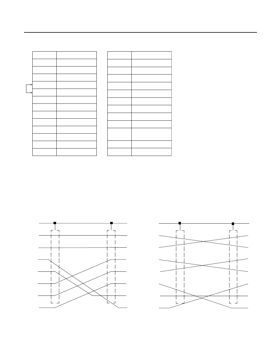
* Pin numbers 18, 23, and 25 are for use with the teaching pendant signal. Do not connect these pins.
• Pin numbers 4 and 5 are short-circuited.
n
n
n
n
nRS232C Cable
Use RS232C cable pin configuration (between controller and computer serial port)
4.
Teaching/RS232C Connector (D-Sub 25 DTE Special *)
Chapter 1.
Setting Up
l
Earth
l
l
l
l
l
l
1
2
3
TXD
RXD
RTS
CTS
DTR
GND
DSR
l
4
5
6
7
20
l
l
l
l
l
l
l
l
Earth
RXD
TXD
DTR
GND
DSR
RTS
CTS
2
3
4
5
6
7
8
Shield
RS232C Adapter
(25 Pin Male)
IBM PC
(9 Pin Female)
Earth
TXD
RXD
RTS
CTS
DSR
GND
DTR
Earth
l
l
l
l
l
l
l
l
l
l
l
l
l
l
l
l
TXD
RXD
RTS
CTS
DSR
GND
DTR
2
1
3
4
5
6
7
20
1
2
3
4
5
6
7
20
IBM PC
(25 Pin Female)
RS232C Adapter
(25 Pin Male)
Pin No.
Signal
1
FG
2
TXD
3
RXD
4
(RTS)
5
(CTS)
6
DSR
7
SG
8
NC
9
NC
10
NC
11
NC
12
NC
13
NC
Pin No.
Signal
14
NC
15
NC
16
NC
17
NC
18
+6.2V Output
19
NC
20
DTR
21
NC
22
NC
23
Emergency Stop
Switch (EMG.SW)
24
NC
25
0V (+6.2V)
*
*
*