Chapter 1. setting up – IAI America S-SEL-E User Manual
Page 31
Page 29
2.
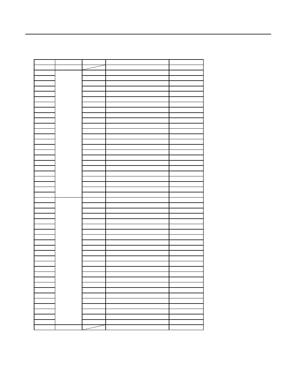
Interface List
I/O Connector
(NPN-Sinking)
Chapter 1. Setting Up
* Emergency Stop (normally
closed). To release the emer-
gency stop, short circuit the
jumper post with a jumper pin or
connect pin 2B and pin 25B.
Refer to Supplement 6.
* Pin No.3A (Port No.003) and Pin
No.3B (Port No.004) cannot be
used as user input.
* Connector:
Sumitomo 3M7950-6500SC or
Yamaichi FAP-5001-1202
Pin No.
Category
Port No.
Function
Cable
1A
P24
---
1-Brown
1B
Input
000
External Start Input
1-Red
2A
001
User Input
1-Orange
2B
002
Emergency Stop b Contact Input *
1-Yellow
3A
003
SystemReserve
1-Green
3B
004
SystemReserve
1-Blue
4A
005
User Input
1-Purple
4B
006
User Input
1-Gray
5A
007
User Input
1-White
5B
008
PRG No. 1 (User Input)
1-Black
6A
009
PRG No. 2 (User Input)
2-Brown
6B
010
PRG No. 4 (User Input)
2-Red
7A
011
PRG No. 8 (User Input)
2-Orange
7B
012
PRG No. 10 (User Input)
2-Yellow
8A
013
PRG No. 20 (User Input)
2-Green
8B
014
PRG No. 40 (User Input)
2-Blue
9A
015
User Input
2-Purple
9B
016
User Input
2-Gray
10A
017
User Input
2-White
10B
018
User Input
2-Black
11A
019
User Input
3-Brown
11B
020
User Input
3-Red
12A
021
User Input
3-Orange
12B
022
User Input
3-Yellow
13A
023
User Input
3-Green
13B
Output
300
Emergency Stop/Alarm Output
3-Blue
14A
301
Ready Output
3-Purple
14B
302
User Output
3-Gray
15A
303
User Output
3-White
15B
304
User Output
3-Black
16A
305
User Output
4-Brown
16B
306
User Output
4-Red
17A
307
User Output
4-Orange
17B
308
User Output
4-Yellow
18A
309
User Output
4-Green
18B
310
User Output
4-Blue
19A
311
User Output
4-Purple
19B
312
User Output
4-Gray
20A
313
User Output
4-White
20B
314
User Output
4-Black
21A
315
User Output
5-Brown
21B
316
User Output
5-Red
22A
317
User Output
5-Orange
22B
318
User Output
5-Yellow
23A
319
User Output
5-Green
23B
320
User Output
5-Blue
24A
321
User Output
5-Purple
24B
322
User Output
5-Gray
25A
323
User Output
5-White
25B
N24
---
5-Black