Configuring ac 1 – H3C Technologies H3C WX3000E Series Wireless Switches User Manual
Page 228
214
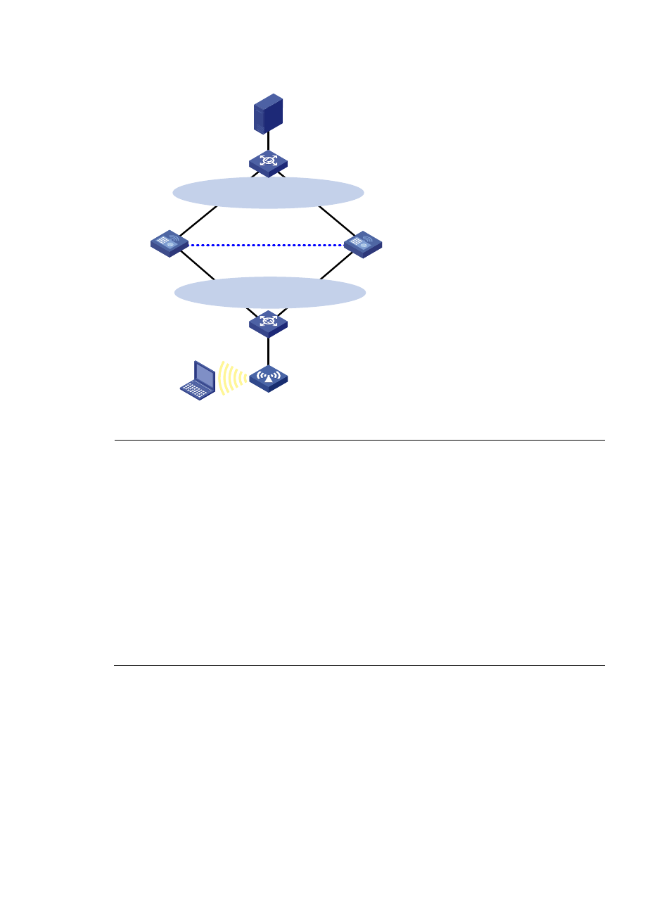
Figure 112 Network diagram
NOTE:
•
Configure IP addresses for the server, client, switches, and ACs and make sure that they have IP
connectivity between each other.
•
Make sure that the client can access the authentication server through AC 1 and AC 2, respectively.
•
Configure VRRP group 1 and VRRP group 2 to implement backup for downstream and upstream links
respectively. For more information about VRRP, see
High Availability Configuration Guide.
•
On the RADIUS server, specify the access device's IP address as the virtual IP address of VRRP group 2.
•
For more information about stateful failover, see
High Availability Configuration Guide.
•
You must use consistent device roles for AC stateful failover and VRRP. If you use an AC as the master for
stateful failover, use the AC as the master in a VRRP group, too. Otherwise, in local portal
authentication, the access device cannot push the authentication page according to the SSID. If your
network cannot meet the requirement, for example, the two ACs are configured for load balancing,
related portal-free rules should be configured.
Configuring AC 1
1.
Configure VRRP:
# Create VRRP group 1, and configure the virtual IP address of VRRP group 1 as 16.16.0.8.
[AC1] interface vlan-interface 100
[AC1–Vlan-interface100] vrrp vrid 1 virtual-ip 16.16.0.8
# Set the priority of VLAN-interface 100 in VRRP group 1 to 200.
[AC1–Vlan-interface100] vrrp vrid 1 priority 200
AC 1
(Master)
Failover link
Client
IP: 16.16.0.12/24
AC 2
(Backup)
Vlan-int1
2.2.2.1/24
Vlan-int1
2.2.2.3/24
GE1/0/1
Vlan-int8
8.1.1.3/24
GE1/0/1
Vlan-int8
8.1.1.1/24
VLAN10
Virtual IP address 2:
8.1.1.68/24
Master
Backup
Virtual IP address 1:
16.16.0.8/24
Master
Backup
L2 Switch
L2 Switch
AP
Vlan-int1
2.2.2.2/24
Vlan-int100
16.16.0.1/24
Vlan-int100
16.16.0.3/24
RADIUS server
IP: 8.1.1.2/24
- H3C WX5500E Series Access Controllers H3C WX3500E Series Access Controllers H3C WX2500E Series Access Controllers H3C WX6000 Series Access Controllers H3C WX5000 Series Access Controllers H3C LSWM1WCM10 Access Controller Module H3C LSUM3WCMD0 Access Controller Module H3C LSUM1WCME0 Access Controller Module H3C LSWM1WCM20 Access Controller Module H3C LSQM1WCMB0 Access Controller Module H3C LSRM1WCM2A1 Access Controller Module H3C LSBM1WCM2A0 Access Controller Module H3C WA3600 Series Access Points H3C WA2600 Series WLAN Access Points H3C S10500 Series Switches H3C S5800 Series Switches H3C S5820X Series Switches H3C S12500 Series Switches H3C S9500E Series Switches H3C MSR 5600 H3C MSR 50 H3C MSR 3600 H3C MSR 30 H3C MSR 2600 H3C MSR 20-2X[40] H3C MSR 20-1X H3C MSR 930 H3C MSR 900 H3C SR8800 H3C SR6600-X H3C SR6600 H3C SecPath F5020 H3C SecPath F5040 H3C VMSG VFW1000