Basic concepts – H3C Technologies H3C WX3000E Series Wireless Switches User Manual
Page 169
155
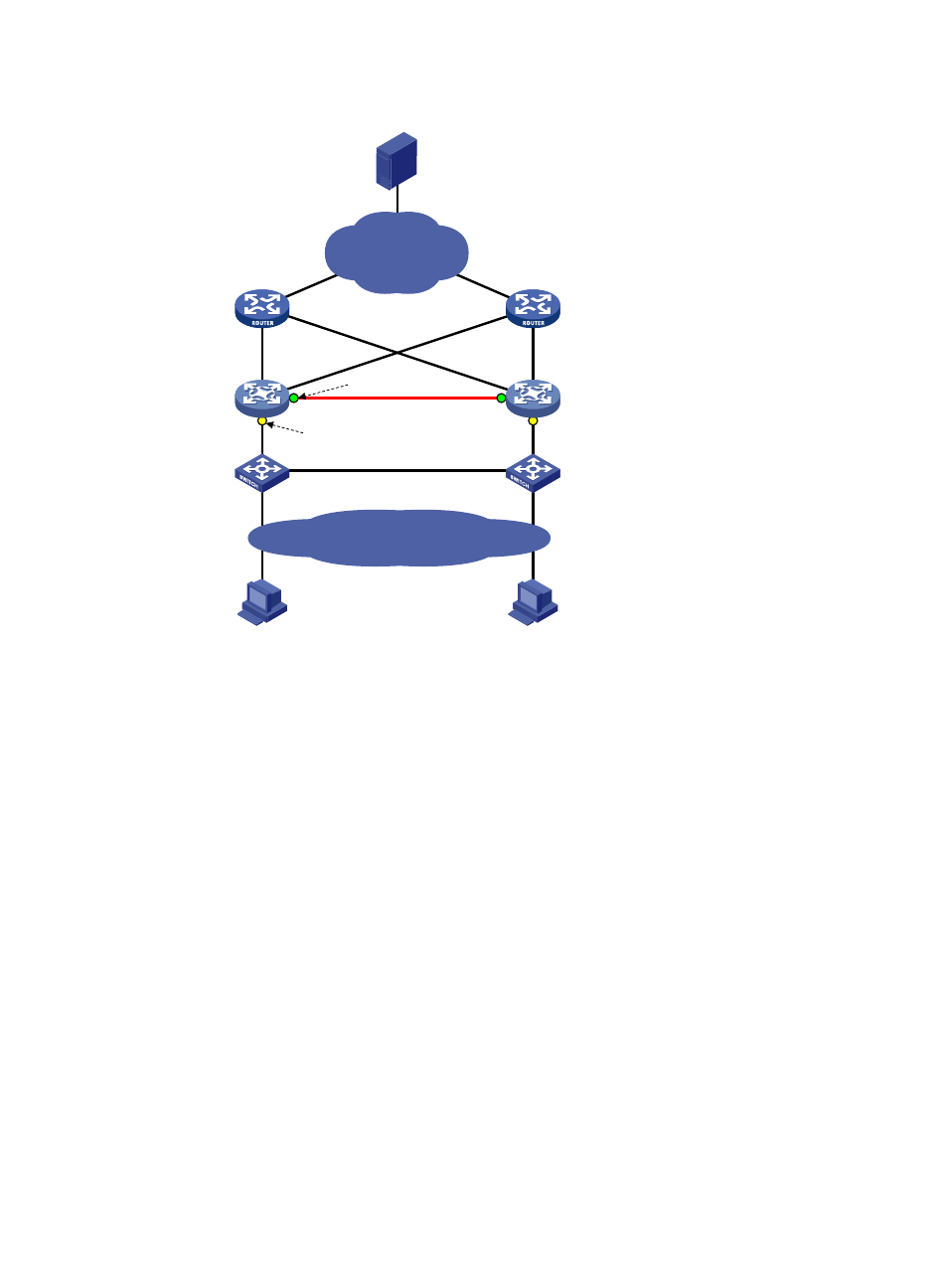
Figure 74 Network diagram for portal stateful failover configuration
As shown in
, users have to pass portal authentication to access the Internet. To avoid portal
service interruption caused by single point failures, you can deploy two access devices (Gateway A and
Gateway B) and configure the portal stateful failover function on them, so that they back up the portal
online user information of each other through the failover link. When one of them (Gateway A or
Gateway B) fails, the other can guarantee the normal data communication of the online portal users and
perform portal authentication for new portal users.
Basic concepts
1.
Device states
{
Independence—A stable running status of a device when it does not establish the failover link
with the other device.
{
Synchronization—A stable running status of a device when it establishes the failover link with
the other device successfully and is ready for data backup.
2.
User modes
{
Stand-alone—Indicates that the user data is stored on the local device only. Currently, the local
device is in independence state or it is in synchronization state but has not synchronized the
user data to the peer device yet.
{
Primary—Indicates that the user logs in from the local device, and the user data is generated
on the local device. The local device is in synchronization state and ready for receiving and
processing packets from the server.
{
Secondary—Indicates that the user logs in from the peer device, and the user data is
synchronized from the peer device to the local device. The local device is in synchronization
Router A
Gateway A
Router B
Gateway B
Failover link
Intranet
Host A
Host B
Switch A
Switch B
Stateful failover
interface
Portal enabled
Internet
Server
- H3C WX5500E Series Access Controllers H3C WX3500E Series Access Controllers H3C WX2500E Series Access Controllers H3C WX6000 Series Access Controllers H3C WX5000 Series Access Controllers H3C LSWM1WCM10 Access Controller Module H3C LSUM3WCMD0 Access Controller Module H3C LSUM1WCME0 Access Controller Module H3C LSWM1WCM20 Access Controller Module H3C LSQM1WCMB0 Access Controller Module H3C LSRM1WCM2A1 Access Controller Module H3C LSBM1WCM2A0 Access Controller Module H3C WA3600 Series Access Points H3C WA2600 Series WLAN Access Points H3C S10500 Series Switches H3C S5800 Series Switches H3C S5820X Series Switches H3C S12500 Series Switches H3C S9500E Series Switches H3C MSR 5600 H3C MSR 50 H3C MSR 3600 H3C MSR 30 H3C MSR 2600 H3C MSR 20-2X[40] H3C MSR 20-1X H3C MSR 930 H3C MSR 900 H3C SR8800 H3C SR6600-X H3C SR6600 H3C SecPath F5020 H3C SecPath F5040 H3C VMSG VFW1000