Static local area network addressing, The ip/router configuration menu, Ip/r – Verilink XEL XSP-100 SHARK IAP (9SA-USRS-9.0R1.02) Product Manual User Manual
Page 83: Outer, Onfiguration, Able, Ynamic, Ontrol, Rotocol information table
Chapter 5: Graphical User Interface (GUI/WEB) Configuration Pages
SHARK™ IAD User's Guide
XEL P/N & Release: 9SA-USRS-9.0R1.02
Chapter 5-29
Static Local Area
Network Addressing
If you want to manually assign the addressing schemes for all the workstations that
are connected to the same Local Area Network as your SHARK™ IAD's Fether
port, you must turn DHCP off. The addresses that you assign for each workstation
must be in the same subnet as the LAN to which the SHARK™ IAD's Fether port
is connected.
Record the addresses that you assign to each workstation and store the record in a
safe place. For a discussion about how to enter the addresses into a PC type
workstation see the Getting Started chapter of this manual or the Getting started
booklet that came with your SHARK™ IAD.
If you want the SHARK™ IAD to assign the addresses automatically, go to DHCP
Dynamic Host Control Protocol (Auto Addressing).
DHCP Dynamic
Host Control
Protocol (Auto
Addressing)
If you want the SHARK™ IAD to automatically assign the addressing schemes
for the workstations that are connected to the same Local Area Network as your
SHARK™ IAD's Fether port, you must enable DHCP. To use DHCP
addressing you must define the following parameters:
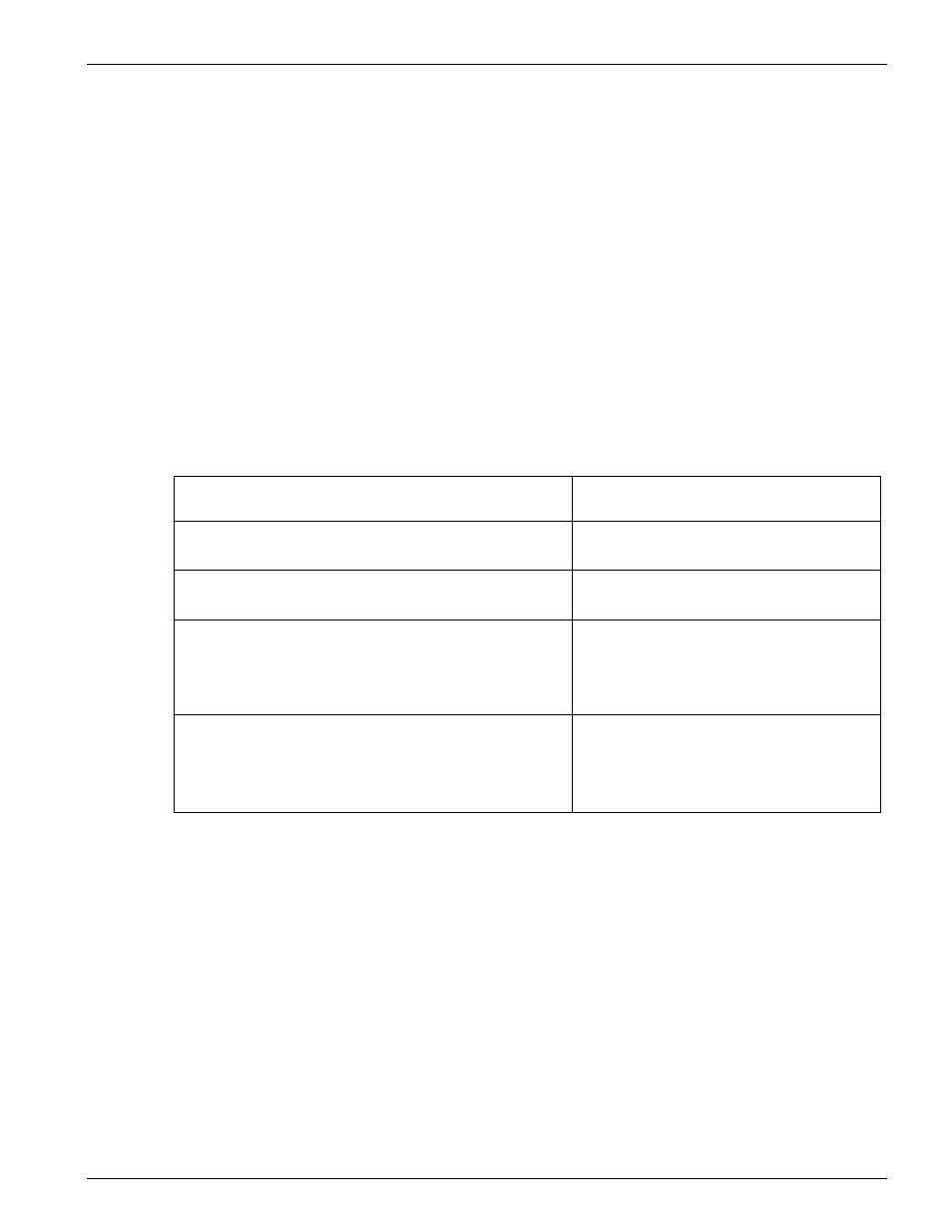
Table 8:
Dynamic Host Control Protocol information table
DHCP Settings
Choose: Off, Server, or Relay-Agent:
Start Address:
The first IP address the SHARK™ IAD should assign:
End Address:
The last IP address the SHARK™ IAD should assign:
Lease Time:
The time period for which DHCP address leases will be
issued. The default lease time is one hour
00:01:00:00.
Server Address:
The IP address of the DHCP server to which the SHARK™
IAD will relay DHCP requests from clients connected to the
same LAN as the Fether port (only needed if configured for
relay-agent)
T
HE
IP/R
OUTER
C
ONFIGURATION
M
ENU
Once the necessary information has been gathered, from the home page, click on
the Router's Config button as shown in Figure 23. The IPRouter menu is
displayed. As shown in Figure 24, it has 10 submenu buttons that are used to
configure the various parts of the IPRouter.