Fcc required emi filters, Fcc required emi filters -9, Igure – Verilink XEL XSP-100 SHARK IAP (9SA-USRS-9.0R1.02) Product Manual User Manual
Page 29: Cat 5, Cable used for, Transmission, Filter installation, Ower module, Power cable
Chapter 2: Installation
SHARK™ IAD User's Guide
XEL P/N & Release: 9SA-USRS-9.0R1.02
Chapter 2-9
FCC
REQUIRED
EMI
FILTERS
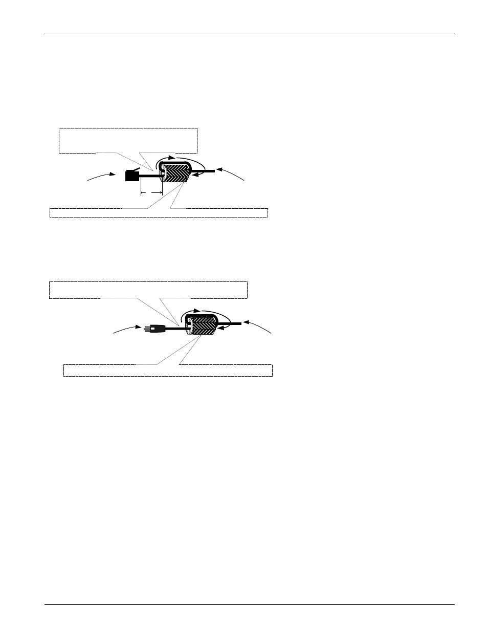
Figure 6 and Figure 7 show how to install the EMI Filters that come with the
Power and T1 modules. Failure to install these filters as shown may void the
FCC licensing of your SHARK™ IAD unit.
CAT 5 cable transporting
T1 signals. Loop cable
through the filter as shown.
T1 connector that
connects to T1 module
9SA-T100-000
XEL part number 180-A2003-01 supplied with module 9SA-T100-000
2"
FCC requirements are that the EMI filter be
installed by the customer approximately 2" from
the end of the T1 input cable as shown.
Figure 6:
CAT 5 cable used for T1 transmission EMI filter installation
Fcc requirements are that the EMI filter be installed by the customer
approximately 2" to 3" from the end of the DC input cable as shown.
DC power cable from the AC External
Power supply 9SA-PWEX-000. Loop
cable as shown.
DCV Power connector that
connects to Power module
9SA-PW00-000
XEL part number 180-A2003-01 supplied with module 9SA-PW00-000
Figure 7:
Power module DCV power cable EMI filter installation