General description, Hardware specifications, Physical size – Verilink XEL XSP-100 SHARK IAP (9SA-USRS-9.0R1.02) Product Manual User Manual
Page 224: T1 m, Odule, 9sa-t100-v01, 9sa-t100-v02, 9sb-t100-v01 -24, Physical size* -24, Igure, Odule faceplate
Chapter 9- Hardware Specifications
Chapter 9-24 XEL P/N & Release: 9SA-USRS-9.0R1.02 SHARK™ IAD User's Guide
T1 Module,
9SA-T100-V01, 9SA-T100-V02, 9SB-T100-V01
RX
9SB-T100-000
XEL
TX
T1 MON
T1
ALARM
LO
C
RE
M
LP
BK
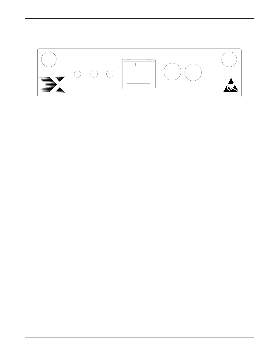
Figure 18:
T1 Module faceplate
G
ENERAL
D
ESCRIPTION
There are multiple types of T1 interface cards for use in the positions identified
as WAN and LAN. They are identified as follows:
• The 9SB-T100-V01 card is a T1 interface module that may be inserted into
either of the two WAN interface ports or the two LAN interface ports on the
front of the IAD. When in the LAN position, the FDL link will not function
as a communication channel.
• The 9SA-T100-V02 card is a T1 interface module that may only be inserted
in the LAN interface ports. The 9SA-T100-V02 card functions identically to
the 9SB-T100-V02 when plugged into the LAN slot. If this card is inserted
into the WAN interface positions, it will continually flash the LED’s on the
face of the card.
The T1 interface consists of four wires in two pairs. These signal wires from the
T1 cable are physically terminated at a MOD-8 connector on the card’s
faceplate, which is wired as a RJ-48C T1 interface. Two Bantam jacks on the
card’s faceplate provides for monitoring both the receive T1 and the transmit T1
signal lines.
This card provides for performance monitoring. See the Alarms and Monitoring
chapter for more details. Communication through the FDL link is supported
when the proper card is in a WAN position and programmed for ESF signaling.
See the FDL configuration in the Graphical User Interface Chapter or the
Command Line Interface Chapter.
H
ARDWARE
S
PECIFICATIONS
Physical size*
Width: 4.25”
Length: 12.66"
Height: 1.0”
Weight: 0.40 lbs
*All measurements include faceplate.