Note on network/cpe mode, Ote on, Etwork – Verilink XEL XSP-100 SHARK IAP (9SA-USRS-9.0R1.02) Product Manual User Manual
Page 114: Mode, Igure, Oice, Onfiguration, Age for, Fxs n, Etwork mode
Chapter 5: Graphical User Interface (GUI/WEB) Configuration Pages
Chapter 5-60
XEL P/N & Release: 9SA-USRS-9.0R1.02
SHARK™ IAD User's Guide
as part of Telephone Company termination equipment, select network. If you
are using this unit on the customer side of the Telephone Company demarcation,
select CPE. Even though the SHARK™ IAD can be used as a Central Office
piece of equipment, it is most widely used at the customer's site as "Customer
Premise Equipment" or CPE. When the SHARK™ IAD is in the "System Voice
CPE" mode the configuration pages in Figure 55 and Figure 56 are used for
configuring the voice modules. The Voice mode in the system menu controls
which page that is to be displayed by allowing the user to configure the
SHARK™ IAD as a network or a CPE unit. Only the system administrator can
change this mode. The SHARK™ IAD is factory shipped in the network Mode.
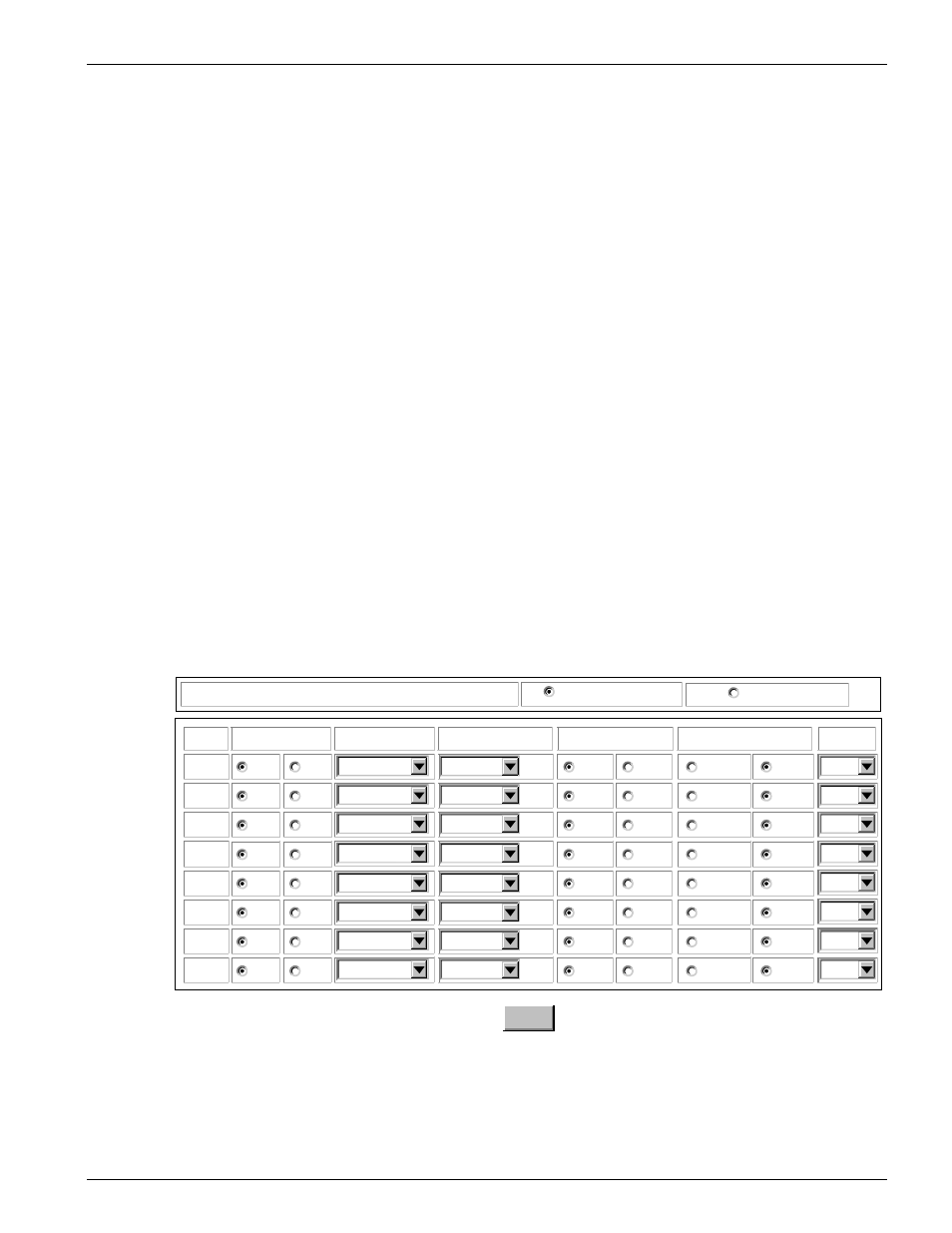
The Voice Network page, see Figure 57 and Figure 58, allows the user full
control over the circuit's Loop Length and wire gauge. The System Network and
CPE Voice pages only differ in that the Voice Network page has a Loop Length
and wire gauge column while the Voice CPE page only has a Gain column.
Table 21 shows the Loop Length and Loop Wire Gauge options. All other Voice
parameters are set the same regardless of the System Voice mode.
N
OTE ON
N
ETWORK
/CPE
MODE
To comply with the specific FCC requirements functionality of the Voice
modules has been separated into the CPE and Network modes.
Do not operate the SHARK™ IAD in the Network mode while installed as
CPE equipment at a customer's premise. Doing such is a violation of your
SHARK™ IAD's FCC licensing.
Voice 1 Configuration (FXS in Network Mode)
operational
not operational
Module Operational Mode:
Circuit
1
2
3
4
5
6
7
8
Impedance
Alarm Processing
600
600
600
600
600
600
600
600
900
900
900
900
900
900
900
900
Loop Length
Loop Wire Gauge
norm
norm
norm
norm
norm
norm
norm
norm
TMB
TMB
TMB
TMB
TMB
TMB
TMB
TMB
State
standby
standby
standby
standby
standby
standby
standby
standby
active
active
active
active
active
active
active
active
0-999ft
26 AWG
0-999ft
26 AWG
0-999ft
26 AWG
0-999ft
26 AWG
0-999ft
26 AWG
0-999ft
26 AWG
0-999ft
26 AWG
0-999ft
26 AWG
FXS
FXS
FXS
FXS
FXS
FXS
FXS
FXS
Signaling
Save
Figure 57:
Voice Configuration Page for FXS Network mode