Igure, Fxs/dpo v, Oice – Verilink XEL XSP-100 SHARK IAP (9SA-USRS-9.0R1.02) Product Manual User Manual
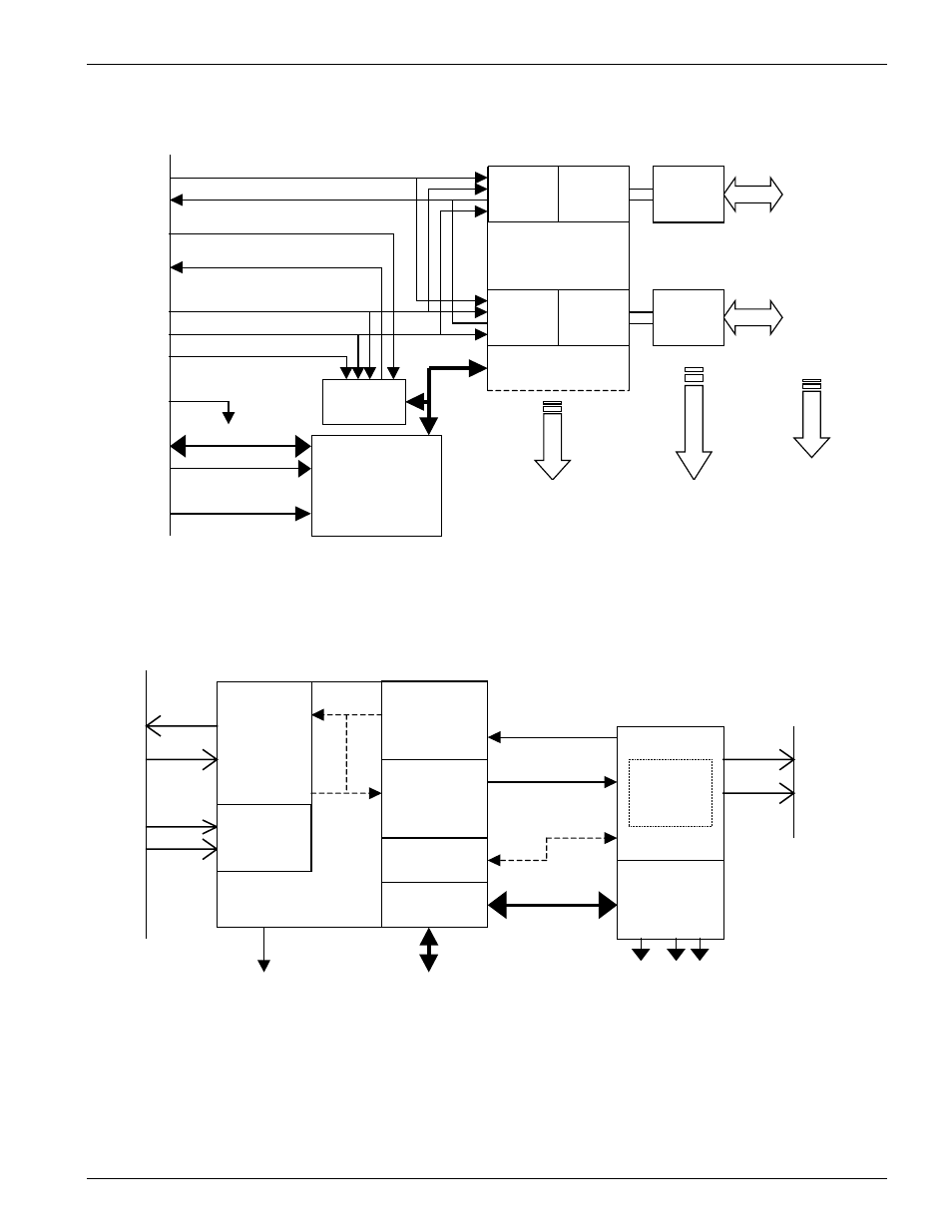
Page 229: Odule, Circuits, Ndividual, Ircuits, Figure 23: fxs/dpo voice module (8 circuits), Figure 24: individual fxs/dpo voice circuits
Chapter 9- Hardware Specifications
SHARK™ IAD User's Guide XEL P/N & Release: 9SA-USRS-9.0R1.02 Chapter 9-29
Com port (5)
Reset line (2)
MCU
controlling
8 circuits
Tdata (1)
Rdata (1)
Frame Strobe (1)
B
a
c
k
P
l
a
n
e
2 wire
Port A
Channel A
digital
conversion
Termination
+ Voice
adjustments
SLIC
Channel B
digital
conversion
Termination
+ Voice
adjustments
SLIC
2 wire
Port B
2 wire
Port C to H
Control bus
FXS Voice Plug – 8 circuits
SF Strobe (1)
Plug Slot Location (2)
Rcv data clock (1)
Signaling
interface
SLAC
Rx signaling (1)
Tx signaling (1)
occupied
Figure 23:
FXS/DPO Voice Module (8 circuits)
Ring Lead
Tip Lead
SLIC controls
and sensors
600/ 900 ohm
2/4-wire
hybrid
network
-24 -48VDC
Ring
volts
Control bus to/from MCU
PCM
Encoding
Decoding
Interrupt ReQuest to MCU
Tdata
Rdata
Frame
Strobe
B
a
c
k
P
l
a
n
e
2-wire
Port
Connector
Transmit
Voice
compensation
Receive
Voice
compensation
AISN
coefficients
SLIC control
registers
Clock
Time Slot
Assignor
(TSA)
Figure 24:
Individual FXS/DPO Voice Circuits
- 1061 T1 Multicast (34-00268) Product Manual (18 pages)
- 2010 (34-00204) Product Manual (15 pages)
- 1558A (34-00228) Product Manual (39 pages)
- 1558D (34-00255) Product Manual (42 pages)
- 210 (34-00196) Product Manual (9 pages)
- 2000 (34-00182) Product Manual (58 pages)
- 300 (34-00199) Product Manual (9 pages)
- 2048 (34-00179) Product Manual (33 pages)
- 400 (34-00222) Product Manual (9 pages)
- 2100 (34-00187) Product Manual (19 pages)
- 7200p Series IAD (34-00334.B) Product Manual (311 pages)
- APS 2000 T1 Line Protection (880-502411-001) Product Manual (87 pages)
- AS200 (896-502379-001) Product Manual (112 pages)
- AS420 (34-00294) Product Manual (28 pages)
- AS56/56Plus (896-502588-001) Product Manual (130 pages)
- 9000 Series (34-00271) Product Manual (440 pages)
- AS2000: The Basics (880-502981-001) Product Manual (179 pages)
- Access Manager 2000 (896-502037-001) Product Manual (400 pages)
- ConnecT 56K DSU (896-502110-001) Product Manual (88 pages)
- AS4000 (34-00244) Product Manual (210 pages)
- C150 (880-502893-001) Product Manual (135 pages)
- Craft Interface (No Part Number) Product Manual (8 pages)
- DDS Lite (34-00295.C) Product Manual (19 pages)
- DCSU 2911 (880-502647-001) Product Manual (79 pages)
- DIDCSU 2912 (880-502646-001) Product Manual (107 pages)
- DIU 2130 (880-503297-001) Product Manual (101 pages)
- DIU 2131 (880-502765-001) Product Manual (31 pages)
- FrameStart FSE (34-00291.F) Product Manual (49 pages)
- DPRI 2922 (880-503142-001) Product Manual (91 pages)
- HDM 2180 (880-503048-001) Product Manual (79 pages)
- HDM 2182 (880-502925-001) Product Manual (81 pages)
- IMUX (880-503137-001) Product Manual (48 pages)
- FrameStart FSM (34-00299.E) Product Manual (153 pages)
- TAC 2010 (880-503298-001) Product Manual (65 pages)
- M1-3 (880-503136-001) Product Manual (75 pages)
- NCC 2130 (880-503285-001) Product Manual (61 pages)
- NCM 2000 (880-502623-001) Product Manual (91 pages)
- NetPath 2000 Product Manual (30 pages)
- PRISM 3000 (34-00184) Product Manual (45 pages)
- PRISM 3001 (34-00186) Product Manual (58 pages)
- PRISM 3002 (34-00277) Product Manual (52 pages)
- Net Engine (3150-30626-001) Product Manual (323 pages)
- PRISM 3021 (34-00262) Product Manual (47 pages)
- PRISM 3010 Dual DSX-1 (34-00250.2) Product Manual (22 pages)
- PRISM 3060-10 (34-00252.4) Product Manual (76 pages)