Figure 5-32, Pca connections and cables – Gasboy Atlas Start-up User Manual
Page 99
MDE-4334D Atlas™ Start-up and Service Manual · July 2013
Page 5-39
Atlas 8800 Parts
Electronic and Electrical Components
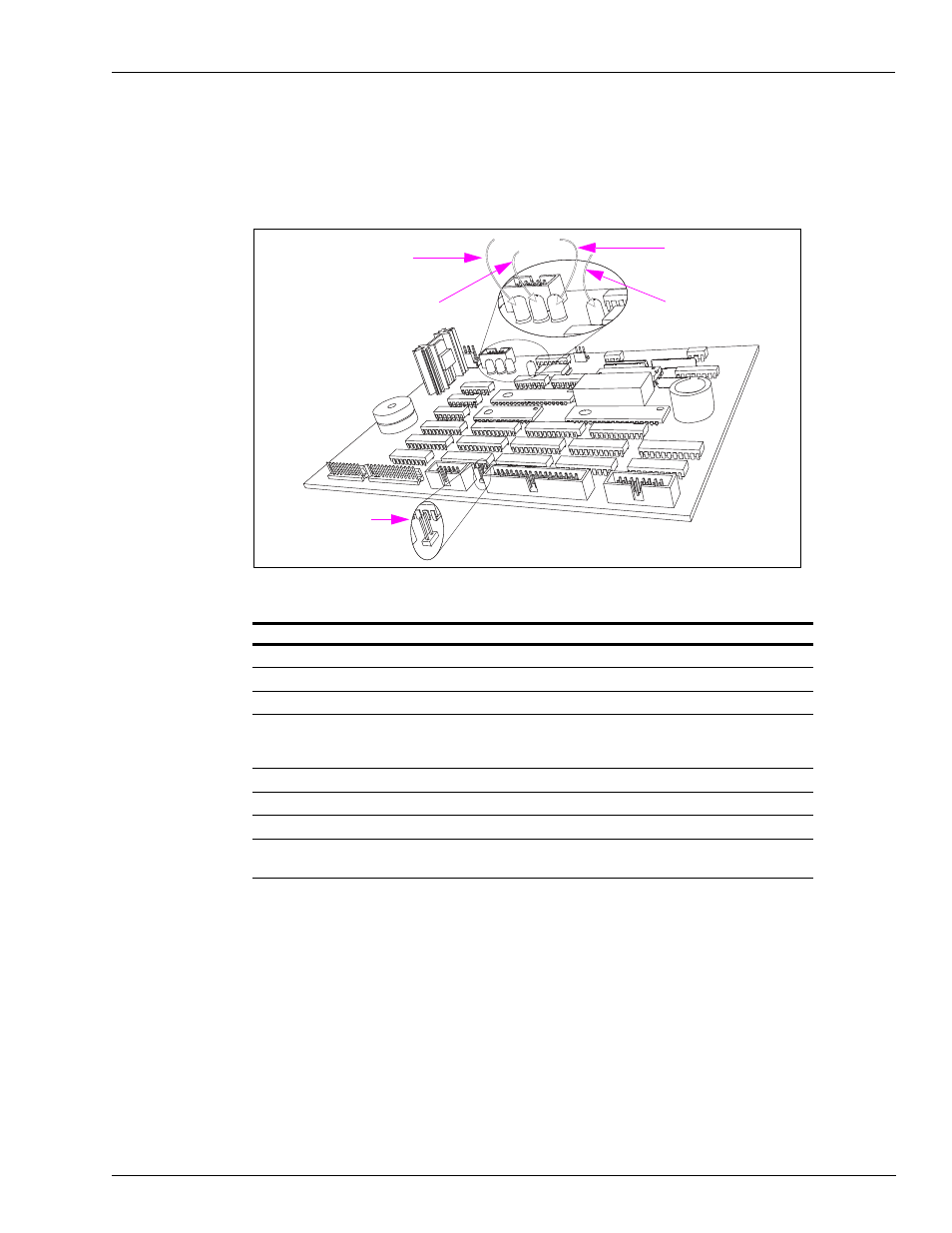
shows the Hydraulic Interface that contains assemblies and components related to
customer information on the Pump Controller PCA (T20092-G1).
Figure 5-32: Atlas 8800 Pump Controller (T20092)
CR-2
Blink = Transmitting Data
CR-1
ON = Two-wire Reversed
CR-4
Blink = Receiving Data
CR-3
ON = CPU Running
JP-1 Jumper On at
Power Up = Master
Reset
PCA Connections and Cables
Connector #
Through Cable To Assembly
At Connector #
P201 (10-pin)
N/A
N/A
N/A
P202 (13-pin)
N/A
N/A
N/A
P203 (10-pin)
R19951-G1
T17549-G1
P901A (10)
P204 (34-pin)
T17768-G1
T17701-G1 or T18981-G1,
Standard LCD Display
P801 (34) (Side A)
(2 places) and (Side B)
(2 places)
P205 (16-pin)
R19952-G1
T18994-G1
P305 (16)
P206 (5-pin)
R19939-G1
T18994-G1
P306 (5)
P207 (10-pin)
R19951-G1
T18994-G1
P307 (10)
P208 (3-pin)
R20412-G3
J402 Field Wiring
P402A (2)
P402 (3)
This PCA contains a firmware chip that holds base instructions for the operation of the unit.
LEDs are provided to alert the technician during diagnostics, regarding POS problems,
processor function, or reversed polarity of the two-wire system feed wires.
The board receives +14 VDC from the Hydraulic Interface PCA. Customer programmable and
5-button preset as well as the Manager Keypad (except for ATC) are connected directly to this
PCA. It supplies +5 VDC to the Hydraulic Interface PCA.