Pulser drive assembly, Pulser drive assembly -54, Service tips – Gasboy Atlas Start-up User Manual
Page 114: Pulser, I.s barrier
Page 5-54
MDE-4334D Atlas™ Start-up and Service Manual · July 2013
Electronic and Electrical Components
Pulsers
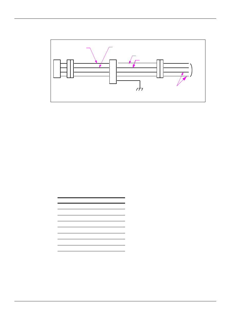
Figure 5-49: Pulser and I.S Barrier Test Points
Pulser
Gray or White
Amber or Red
Yellow or Blue
Brown or Black
I.S Barrier
Point A
+150 VDC With Plug Disconnected
+12 VDC With Plug Connected
Gray
Amber
Yellow
Brown (Ground)
Point B
+150 VDC
Pulser Return
Pulser Feed
Pulser Data
Pulser Data
To C.D.
Module
Chassis Ground
All measurements are made to point A or B at the respective I.S Barrier.
+75 VDC
+5 VDC for Optimum Only
+5 VDC for Optimum Only with Plug Connected
Pulser Drive Assembly
This section explains about the pulser drive assembly.
Special Note for Canadian Installations
An O-ring is used on the shaft in Canadian installations. If squealing is noted, lubricate the
O-ring with silicone grease. When replacing a meter, align the lower drive collar to the meter
shaft to reduce the potential for binding.
Service Tips
• During shipment, T18350-G3 Pulsers are restrained by a tie-wrap and must be removed
during installation. If the tie-wrap is discovered on the pulser during service, it must be
removed. A tie-wrap left in place can result in binding of the pulser shaft.
• Event Logs can be used to identify a specific pulser during troubleshooting pulser errors
such as 20, 5047, 5049, and 5050. Pulser locations are designated by ePulserX. To
determine the location of the pulser, refer to the following table:
Note: Event Logs are available only for Atlas 8800 units.
Pulser Name Side of Unit Product Pulser
ePulser1
1
1
ePulser2
1
2
ePulser3
1
3
ePulser4
1
4
ePulser5
2
1
ePulser6
2
2
ePulser7
2
3
ePulser8
2
4