Pca connections and cables (atlas e85 only) – Gasboy Atlas Start-up User Manual
Page 84
Page 5-24
MDE-4334D Atlas™ Start-up and Service Manual · July 2013
Electronic and Electrical Components
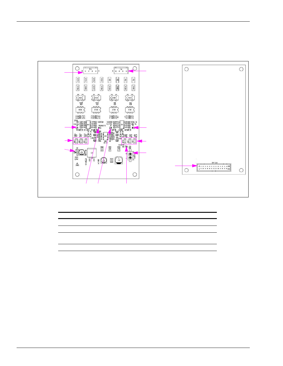
PCAs
shows Valve Interface Board (M11480A001).
Figure 5-19: Valve Interface Board [M11480A001 (Atlas E85 Only)]
P1
D3 SLOW1
JJ1, JJ2, JJ3
P2402
D1 +24 V
D4 FAST1
D5 SLOW2
D2 +5 V
JJ4, JJ5, JJ6
D6 FAST2
P2
P7105
Component Side
Solder Side
PCA Connections and Cables (Atlas E85 Only)
Connector # Through Cable
To Assembly
At Connector #
P1 (4)
M04850A010
Atlas CPU (M06333A002)
P1 (6)
P2 (4)
M04850A010
Atlas CPU (M06333A002)
P2 (6)
P2402 (2)
M07141A003
+24 V Power Supply (M04161B005) Red - (+)
Black - (-)
P7105 (26)
Cable on M06031A001 Valve Controller (M06031A001)
P6105 (26)
Due to different tolerances in components and proportional valve coils, jump jacks JJ1 through
JJ6 (JJ1 through JJ3 affect side 1, JJ4 through JJ6 affect side 2) were added to allow adjusting
the SLOW flow rate. If the SLOW flow rate is too slow, adding a jumper on one of these jump
jacks will increase the valve drive output in SLOW flow mode. Each jumper added increases
the drive output (maximum 3 per hose outlet). They do not affect FAST (or full) flow. If
jumpers have been added and the SLOW flow is too fast (for example, over run of presets),
removing a jumper will decrease the drive output in SLOW flow mode.