Servicing rotor and shaft assembly, Servicing rotor and shaft assembly -57, Warning – Gasboy Atlas Start-up User Manual
Page 177
MDE-4334D Atlas™ Start-up and Service Manual · July 2013
Page 6-57
Pumping Unit
Hydraulic/Mechanical Components
Servicing Rotor and Shaft Assembly
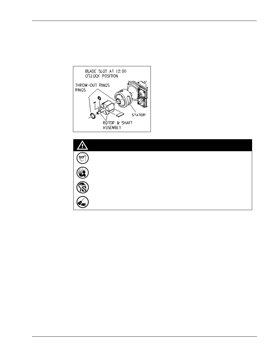
The rotor and shaft assembly is the heart of the pumping unit. It creates the flow and pressure
supplied by the pump.
Figure 6-30: Rotor and Shaft Assembly
• Wear eye protection. Residual pressure and entrapped fuel may still be present
and may drain or spray while removing the parts.
• Fire and explosion could result in severe injury or death.
• Test and close the shear valves involved. Shut off power to the unit.
• Remove the parts slowly. Collect fuel in approved containers.
• Clean up all spills promptly.
WARNING
Service Tips
• The normal failure mode for pumping elements is excessive wear. Occasionally, a seizure
in the bore can result. Wear/seizure can result in either lower or very low flow, or less
commonly motor stalling, and very occasionally noise.
• If the pumping elements appear with minimal wear and the symptom is noise or low flow,
usually there is an installation issue starving the pump or an issue with the Bypass/PRV,
Control Valve, or a component downstream.
• Avoid introducing contamination into the unit while inspecting or replacing the pumping
elements, including the rotor and shaft. Always use the strainer provided and ensure that it
is not clogged.
• Some pumping elements have grooves in the blades manufactured, on purpose. While
replacing the blades, always install new blades in the same orientation.
• A shot of clean oil in the bore after replacing the pumping elements will aid in priming and
initial start-up.
• Excessive belt tension may cause failure of the pumping elements or bearings.