Gasboy Atlas Start-up User Manual
Page 118
Page 5-58
MDE-4334D Atlas™ Start-up and Service Manual · July 2013
Electronic and Electrical Components
Heater
Service Tips
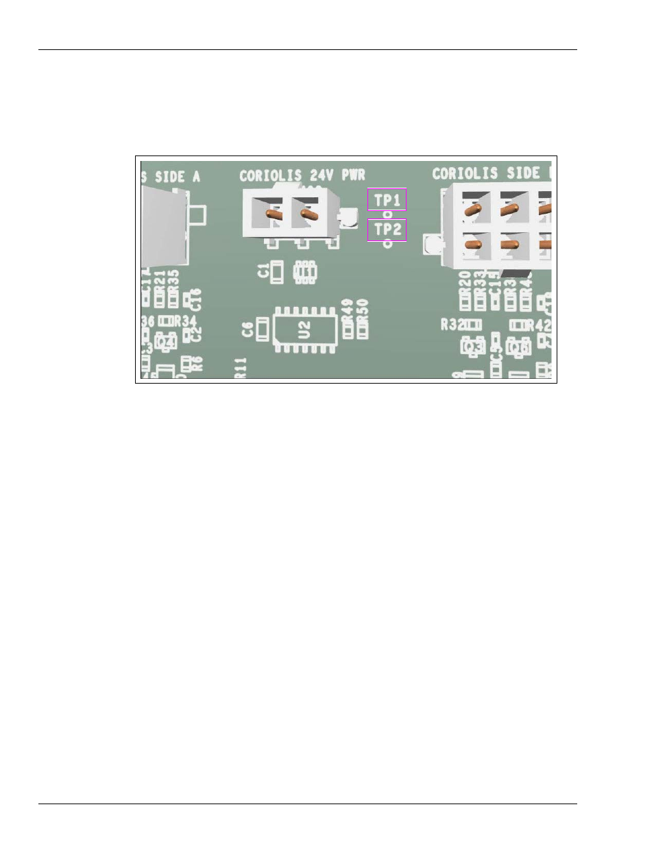
• TP1 and TP2 on the board can be used to verify if the 24 VDC power input is correct
Figure 5-52: TP1 and TP2 on Coriolis Meter Interface Board
• Although the board supplies logic power to the Temperature Control Board, it does not
monitor board’s performance or state. If the Temperature Control Board is inoperative,
check the Coriolis Meter Interface Board and cables between the boards for transference
of 5 VDC.
• Pulser-related error codes could be caused by this board in addition to the cables to and
from the board, as well as the Coriolis Meter or occasionally the PCN.
• Side A and Side B Coriolis Meter inputs have the same jack, so ensure that you connect
the correct meter to the jack on the board. Commercial dispensers use Side A only.
• Several diagnostic LEDs exist on the board. They provide valuable troubleshooting
information. Check the LEDs first before replacing a board as the fault may not be with
the board.