Analyzing pressure drop for pumps and dispensers – Gasboy Atlas Start-up User Manual
Page 137

MDE-4334D Atlas™ Start-up and Service Manual · July 2013
Page 6-17
Measuring Pressure and Vacuum
Hydraulic/Mechanical Components
5
Measure the flow rate and read and record the psi reading on both gauges. Return the pump
handle to the Off position.
6
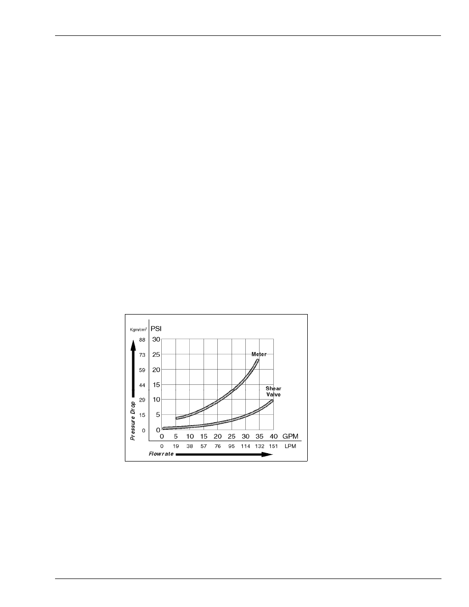
Calculate the pressure drop (difference between the psi readings). For an example of desirable
range, see
.
7
Ensure that the pump handle is in the Off position. If the unit is a dispenser, close the shear
valve. Place the nozzle in an approved container. Lift the pump handle to the On position.
Squeeze the nozzle to bleed the pressure. Return the pump handle to the Off position.
8
Shut off power to the unit.
9
Remove pressure gauges, restore the unit to original condition, purge air, check for leaks, and
return the unit to operation.
Analyzing Pressure Drop for Pumps and Dispensers
Pressure drop across components increases as the total flow rate increases.
• For dispensers, Total System Pressure Drop = Product Lift from bottom of STP to the
dispenser base + Pressure Drop through external piping + Pressure Drop through dispenser
including hose and nozzle.
• Pressure Drop through external piping segments varies depending on the sizes and types
of piping used. It is also affected by the number, sizes, and types of fittings used.
If the total System Pressure Drop at the total flow rate is less than the STP pressure at that flow
rate, the system will develop the required flow rate.
Figure 6-8: Graph for CFT Meter and 1-1/2-inch Shear Valve
Determining if Components Are Faulty
To determine if the components are faulty, proceed as follows:
1
Always check and replace the filter and strainer before performing this test.
2
Determine the dispenser pressure at the inlet and flow rate with the nozzle wide open.
Note: If the pressure at the base of the dispenser is substantially lower, it indicates that the
dispenser is functioning correctly.
