Delta Electronics AC Motor Drive VFD-VE Series User Manual
Page 31
Chapter 2 Installation and Wiring|
2-8
Revision August 2008, 03VE, SW V2.04
To improve power factor and reduce harmonics connect a DC reactor between terminals
[+1, +2]. Please remove the jumper before connecting the DC reactor.
NOTE
Models of 15kW and above have a built-in DC reactor.
Terminals [+2/B1, B2] for connecting brake resistor and terminals [+1, +2/B1] for
connecting external brake unit
Brake unit(optional)
Refer to Appendix B for the use of
spec ial braking resis tor/unit
+2/B1
B2
BR
+2/B1
-
VFDB
BR
Brake resistor(optional)
Connect a brake resistor or brake unit in applications with frequent deceleration ramps,
short deceleration time, too low brake torque or requiring increased brake torque.
If the AC motor drive has a built-in brake chopper (all models of 11kW and below),
connect the external brake resistor to the terminals [+2/B1, B2].
Models of 15kW and above don’t have a built-in brake chopper. Please connect an
external optional brake unit (VFDB-series) and brake resistor. Refer to VFDB series user
manual for details.
Connect the terminals [+(P), -(N)] of the brake unit to the AC motor drive terminals
[+2(+2/B1), (-)]. The length of wiring should be less than 5m with twisted cable.
When not used, please leave the terminals [+2/B1, -] open.
WARNING!
1.
Short-circuiting [B2] or [-] to [+2/B1] can damage the AC motor drive.
Grounding terminals (
)
Make sure that the leads are connected correctly and the AC drive is properly grounded.
(Ground resistance should not exceed 0.1Ω.)
Use ground leads that comply with local regulations and keep them as short as possible.
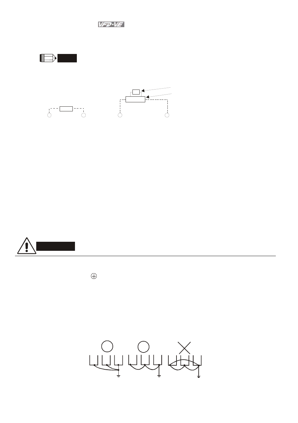
Multiple VFD-VE units can be installed in one location. All the units should be grounded
directly to a common ground terminal, as shown in the figure below. Ensure there are no
ground loops.
good
excellent
not allowed