Delta Electronics AC Motor Drive VFD-VE Series User Manual
Page 203
Chapter 4 Parameters|
4-154
Revision August 2008, 03VE, SW V2.04
4
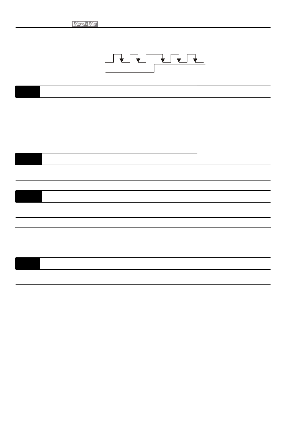
Phase A is a pulse input and phase B is a direction input. (low
input=forward direction, high input=reverse direction)
A
B
FWD
REV
10-16
Output Setting for Frequency Division (denominator)
Unit: 1
Control
mode
VFPG
FOCPG
TQRPG
Factory Setting: 1
Settings
1 to 255
This parameter is used to set the denominator for frequency division. For example, when it is
set to 2 with feedback 1024ppr, PG output will be 1024/2=512ppr.
10-17
PG Electrical Gear A (Channel 1 of PG card)
Unit: 1
Control
mode
VFPG
FOCPG
Factory Setting: 100
Settings
1 to 5000
10-18
PG Electrical Gear B (Channel 2 of PG card)
Unit: 1
Control
mode
VFPG
FOCPG
Factory Setting: 100
Settings
1 to 5000
Rotation speed = pulse frequency/encoder pulse (Pr.10-00) * PG Electrical Gear A / PG
Electrical Gear B.
10-19
PG Position Control Point (Home)
Unit: 1
Control
mode
VFPG
FOCPG
Factory Setting: 0
Settings
0 to 20000
This parameter determines the home position in the position control.
- 1x9 Bi-Directional Transceiver Module OPBD-155F2J1R (7 pages)
- Single Mode SFP Transceiver LCP-1250B4MDRx (14 pages)
- LC-1250xxxx Series (10 pages)
- Human Machine Interface DOP-AS Series (329 pages)
- Analog Output Module DVP04DA-S (2 pages)
- DeviceNet Slave Communication Module IFD9502 (2 pages)
- LCP-155B4MSRx (12 pages)
- High-Speed PCI 12-Axis Motion Control Card PCI-DMC-B01 (528 pages)
- Network Device DVP01PU-S (2 pages)
- GBIC-1250D5MR (12 pages)
- SPBD-1250A4Q1RT (10 pages)
- SILM4015 (1 page)
- LCP-8500A4EDR (14 pages)
- 10GBASE-SR SFP+ Optical Transceiver LCP-10G3A4EDR (16 pages)
- LCP-155A4HSRx (11 pages)
- LCP-1250RJ3SR-L (9 pages)
- SILM320L (1 page)
- LCP-1250RJ3SR-S (9 pages)
- SIL530 (1 page)
- Extension Digital I/O Module DOP-EXIO28RAE (1 page)
- DVP Series PLC DVP04TC-H2 (2 pages)
- 1x9 Bi-Directional Transceiver Module OPBD-155F1J1R (7 pages)
- Distribution Box TAP-CN01/02/03 (2 pages)
- LCP-200A4HSR (9 pages)
- Pulse Generation Unit DVP01PU-H2 (2 pages)
- Power Connection Interface VFD-PSD01 (1 page)
- Programmable Logic Controller DVP04DA-H2 (2 pages)
- Single Mode SFP Transceiver LCP-1250B4QDRx (13 pages)
- LCP-155B4JSRx Series (12 pages)
- Series Temperature Controller DTD Series (2 pages)
- Brake Modules BUE Series (2 pages)
- PLC DVP Series DVP-SX (2 pages)
- Digital Keypad / Display ASD-PU-01A (1 page)
- Multimode SFP Transceiver LCP-1250A4FDRx (14 pages)
- HMU1362M (1 page)
- RPA-01 (1 page)
- THMR1395 (1 page)
- SFBD-155F2J1RM (7 pages)
- Program Transfer Module DVP-PCC01 (1 page)
- RTU-DNET (41 pages)
- AC Servo Drive ASDA-AB (37 pages)
- Digital Keypad / Display ASD-PU-01B (1 page)
- HMR1045 (1 page)
- CANopen Communication Module DVPCOPM-SL (2 pages)
- SPBD-1250B4Q1R (10 pages)