Delta Electronics AC Motor Drive VFD-VE Series User Manual
Page 151
Chapter 4 Parameters|
4-102
Revision August 2008, 03VE, SW V2.04
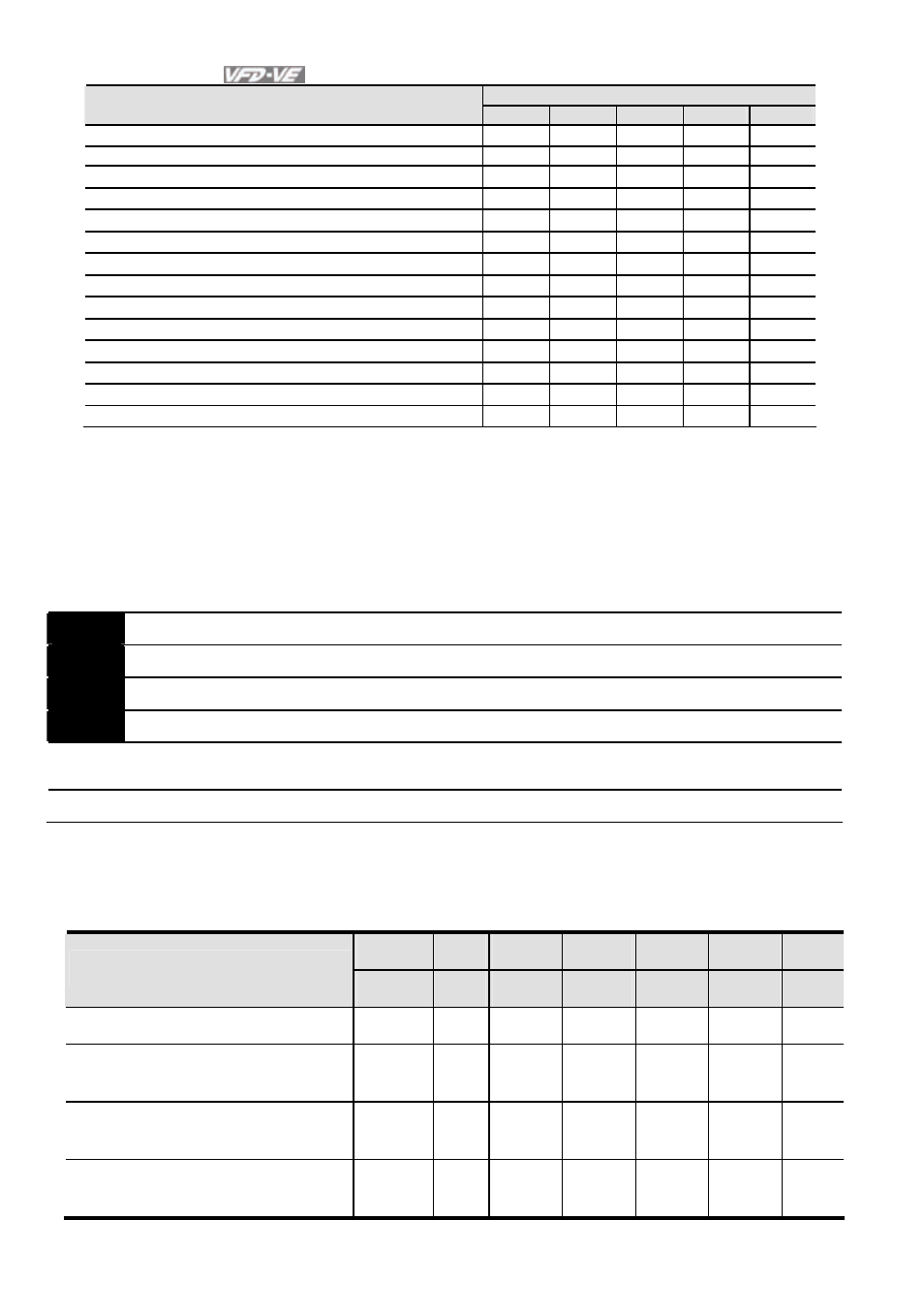
Control Mode
Settings
VF
VFPG
SVC
FOCPG TQRPG
52: Password error (PcodE)
○
○
○
○
○
53:
Reserved
54: Communication error (cE1)
○
○
○
○
○
55: Communication error (cE2)
○
○
○
○
○
56: Communication error (cE3)
○
○
○
○
○
57: Communication error (cE4)
○
○
○
○
○
58: Communication Time-out (cE10)
○
○
○
○
○
59: PU time-out (cP10)
○
○
○
○
○
60: Brake transistor error (bF)
○
○
○
○
○
61: Y-connection/
Δ
-connection switch error (ydc)
○
○
○
○
62: Decel. Energy Backup Error (dEb)
○
○
○
○
○
63: Slip error (oSL)
○
○
○
○
64: Broken belt error (bEb)
○
○
○
○
○
65: Error PID feedback signal of tension (tdEv)
○
○
○
○
○
It will record when the fault occurs and force stopping. For the Lv, it will record when it is
operation, or it will warn without record.
Setting 62: when DEB function is enabled, the drive will execute DEB and record to the Pr.06-
17 to Pr.06-22 simultaneously.
06-23
Fault Output Option 1
Unit: 1
06-24
Fault Output Option 2
Unit: 1
06-25
Fault Output Option 3
Unit: 1
06-26
Fault Output Option 4
Unit: 1
Control
mode
VF VFPG SVC
FOCPG TQRPG
Factory Setting: 0
Settings
0 to 65535 sec (refer to bit table for fault code)
These parameters can be used with multi-function output (set Pr.02-11 to Pr.02-14 to 35-38)
for the specific requirement. When the fault occurs, the corresponding terminals will be
activated (It needs to convert binary value to decimal value to fill in Pr.06-23 to Pr.06-26).
Bit0
Bit1
Bit2
Bit3
Bit4
Bit5
Bit6
Fault code
current Volt.
OL
SYS
FBK
EXI
CE
0: No fault
1: Over-current during acceleration
(ocA)
●
2: Over-current during deceleration
(ocd)
●
3: Over-current during constant
speed (ocn)
●