Flow chart, Ultra plus or iq parameter settings, Appendixes flow chart ultra plus – Rockwell Automation 1398-PDM-xxx IQ Master Version 3.2.4 for IA-2000 and IQ-5000 Positioning Drive Modules, IQ-55 User Manual
Page 384: Iq parameter settings
362
Application Examples • SmartBelt Application
Publication 1398-PM601A-EN-P — October 2000
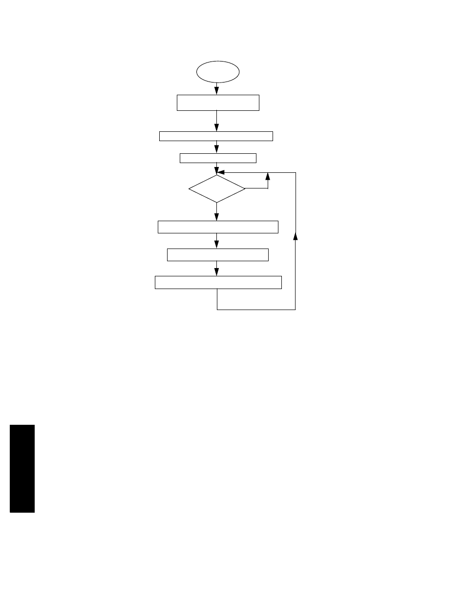
APPENDIXES
Flow Chart
ULTRA Plus
or
IQ Parameter Settings
•
CONFIGSet ULTRA Plus or IQ configuration to accept encoder 2 input for electronic gearing
•
SCALEnumber of encoder counts per unit distance on driven belt
•
SCALE2number of encoder counts per unit distance of belt
•
ACCELallowable acceleration rate without slippage of product
•
VELmotor top speed during correction at machine top speed
TITLE "SBELT"
;Version 3.00 2/29/96
PGMTYPE = MAINPGM
;
ASSIGN OFFSET V1
;OFFSET is desired distance: flight to product
ASSIGN OFFSET2 V2
;
OFFSET = 1.2345
;Set OFFSET in user units (inches, cm, etc.)
OFFSET2 = UTOC1 OFFSET
;Convert OFFSET to encoder counts
; based on SCALE parameter setting
INT1 CONT
;Enable interrupts to capture positions
INT2 CONT
;Input 11 is INT1, Input 12 is INT2
GEAR = 1.00
;Initialize gear ratio
GEAREN ON
;Start tracking the master encoder
WAIT I11 ON
;Wait for first flight
;
MAIN:
;Main loop of program
CALCULATE CORRECTION DISTANCE
START
INITIALIZE VARIABLES
ACTIVATE INTERRUPTS
ACTIVATE ELECTRONIC GEARING
WAIT FOR A FLIGHT
PRODUCT?
PERFORM CORRECTION MOVE
MAKE SURE PRODUCT IS OFF SENSOR
NO
YES