Ultra plus/iq-series block diagram, Tutorial, Ultra plus – Rockwell Automation 1398-PDM-xxx IQ Master Version 3.2.4 for IA-2000 and IQ-5000 Positioning Drive Modules, IQ-55 User Manual
Page 185: Iq-series block diagram, Ba b a, Closed loop control • introduction
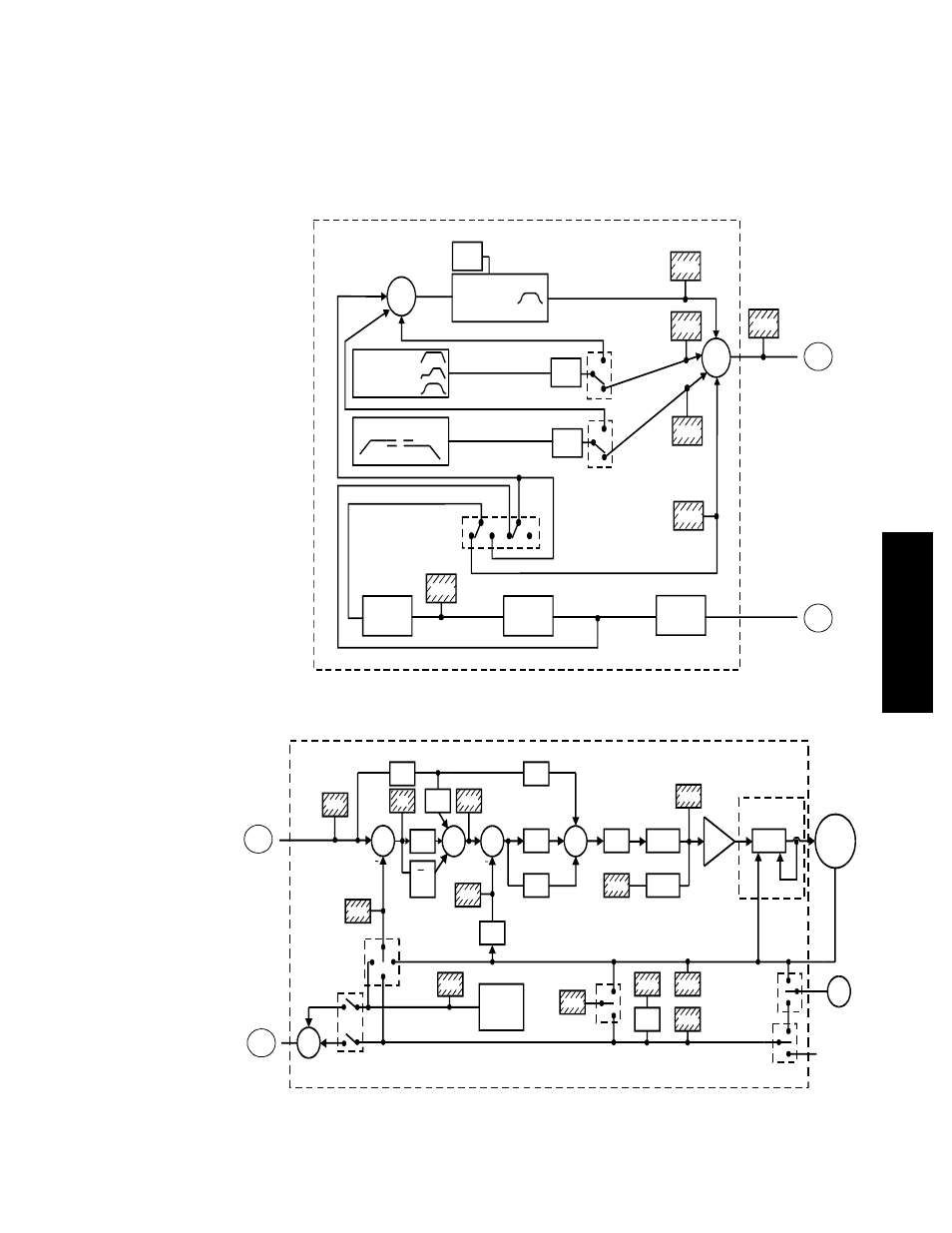
Closed Loop Control • Introduction
163
Publication 1398-PM601A-EN-P — October 2000
TUTORIAL
•
Switches represent choices that are made in the configuration menus.
•
Circles are summing junctions that indicate that the signals flowing in to the circle are summed and
the signal flowing out is the result of the summation.
•
The symbol “S” in a block indicates a Laplace transform. S is a derivative and 1/S is an integral.
For example, the position command (PCMD) flows into a derivative box and the output of that box
is the commanded velocity that is fed into KFF and FGAIN.
ULTRA Plus
/
IQ-Series Block Diagram
BRUSHLESS
MOTOR
GEAR INPUT
AUX.
POSITION
FEEDBACK
OPTION
LATCHED
POSITION
POSITION 2
ENCODER 2
ENCODER 1 OUT
ENCODER 2 IN
STEP AND
DIRECTION IN
FEEDBACK
POSITION
POSN
S
FE
KFF
VCMD
FGAIN
ICMD
POWER
AMPLIFIER
12
BIT
DAC
CURRENT
LIMIT
FILTER
PGAIN
KP
KI
S
IZONE
VEL1
S
AVERAGE
VALUE
IAVE
IGAIN
S
POS3
LPOS
VEL2
POS1
POS2
EXTERNAL FOR IQ 550
See
Block Diagram
Part 2
IQ Functional
Block Diagram
Page 1
PCMD
S
Aux. Position
PROFILE
GENERATOR
MOTION
COMMANDS
FEED
RATE
JOG MOTION COMMANDS
FEED
RATE
GPOS
CAM PROFILE
GENERATOR
MOTION
COMMANDS
FEED
RATE
ELECTRONIC
GEARING
RATIO
TRACKING
SLEW RATE
LIMIT
CGENEN
CJOGEN
CAM EXTERNAL
POSITION SELECT
PCAM
PGEN
PJOG
PEXT
See
Block Diagram
Page 1
PCMD
Aux. Position
Input
B
A
B
A