Chapter 3. rear panel connectors and pinouts, 1 cdm-625 rear panel overview, Chapter 3. rear panel connectors – Comtech EF Data CDM-625 User Manual
Page 71: Pinouts
3–1
Chapter 3. REAR PANEL
CONNECTORS
AND
PINOUTS
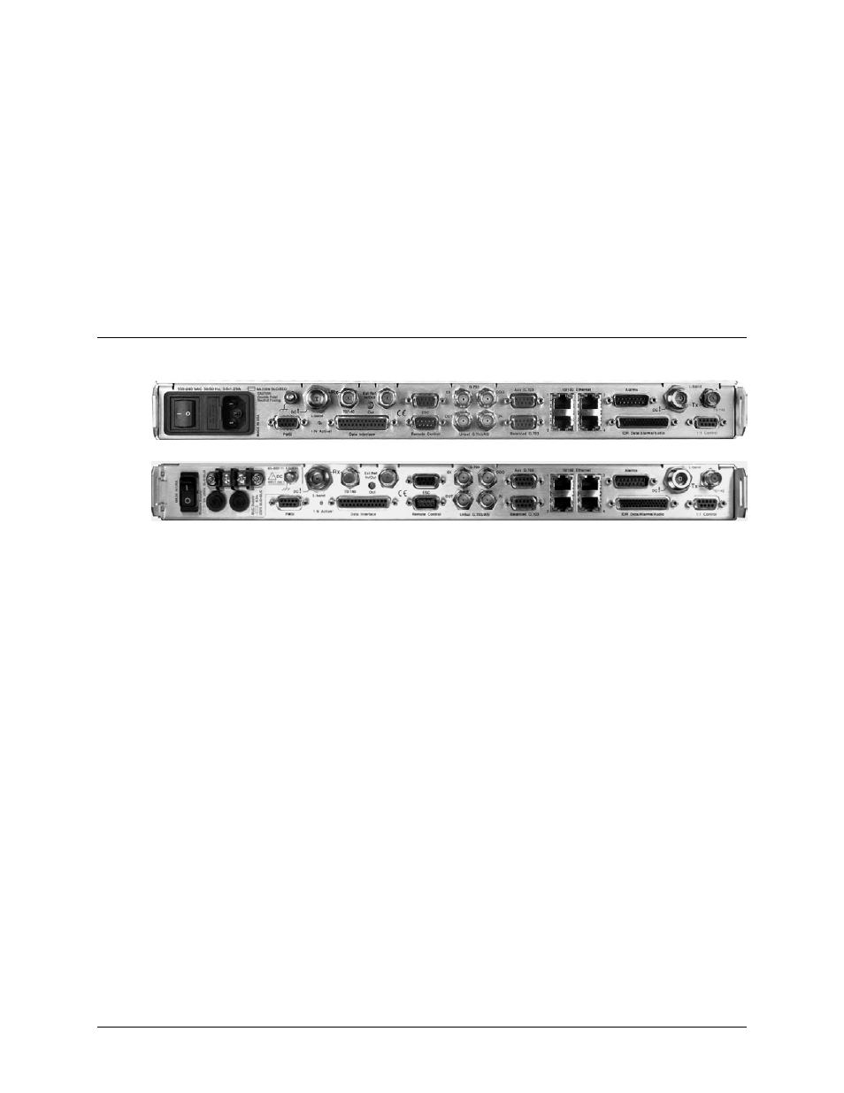
3.1 CDM-625 Rear Panel Overview
Figure 3-1. CDM-625 Rear Panel View
(Top) Standard AC Chassis (CEFD P/N PL/12587-1)
(Bottom) Optional 48V DC Chassis (CEFD P/N PL/12587-2)
The CDM-625 Advanced Satellite Modem’s rear panel, shown in Figure 3-1, provides all
necessary external connections between the modem and other equipment:
•
Section 3.2 details the cabling connections provided on the rear panel interface, grouped
according to service function. Where applicable, the connector’s pinout table is provided.
•
Section 3.3 details the unit’s grounding and power features.
See also other documents in the category Comtech EF Data Equipment:
- CDD-880 (124 pages)
- CDM-800 (130 pages)
- ODMR-840 (184 pages)
- CDM-750 (302 pages)
- CDM-840 (244 pages)
- SLM-5650A (420 pages)
- CTOG-250 (236 pages)
- CDM-700 (256 pages)
- CDM-760 (416 pages)
- CDM-710G (246 pages)
- CDM-600/600L (278 pages)
- CDMR-570L (512 pages)
- CDM-625A (756 pages)
- CDD-564A (240 pages)
- CDD-564L (254 pages)
- CLO-10 (134 pages)
- MCED-100 (96 pages)
- CDMR-570AL (618 pages)
- CDM-600 LDPC (2 pages)
- BUC Power Supply Ground Cable (2 pages)
- MPP70 Hardware Kit for CDM-570L (4 pages)
- MPP50 Hardware Kit for CDM-570L (4 pages)
- CDM-625 DC-AC Conversion (4 pages)
- CDM-625 DC-AC Conversion with IP Packet Processor (4 pages)
- DMDVR20 LBST Rev 1.1 (117 pages)
- DMD2050E (212 pages)
- DMD-2050 (342 pages)
- DMD1050 (188 pages)
- OM20 (220 pages)
- QAM256 (87 pages)
- DD240XR Rev Е (121 pages)
- MM200 ASI Field (5 pages)
- DM240-DVB (196 pages)
- MM200 (192 pages)
- CRS-150 (78 pages)
- CRS-280L (64 pages)
- CRS-170A (172 pages)
- CRS-180 (136 pages)
- SMS-301 (124 pages)
- CiM-25/8000 (186 pages)
- CiM-25 (26 pages)
- CRS-500 (218 pages)
- CRS-311 (196 pages)
- CIC-20 LVDS to HSSI (26 pages)