Table 2-5: implement setup parameters – TeeJet Legacy 6000 Manual User Manual
Page 27
Chapter 2 - System overview
22
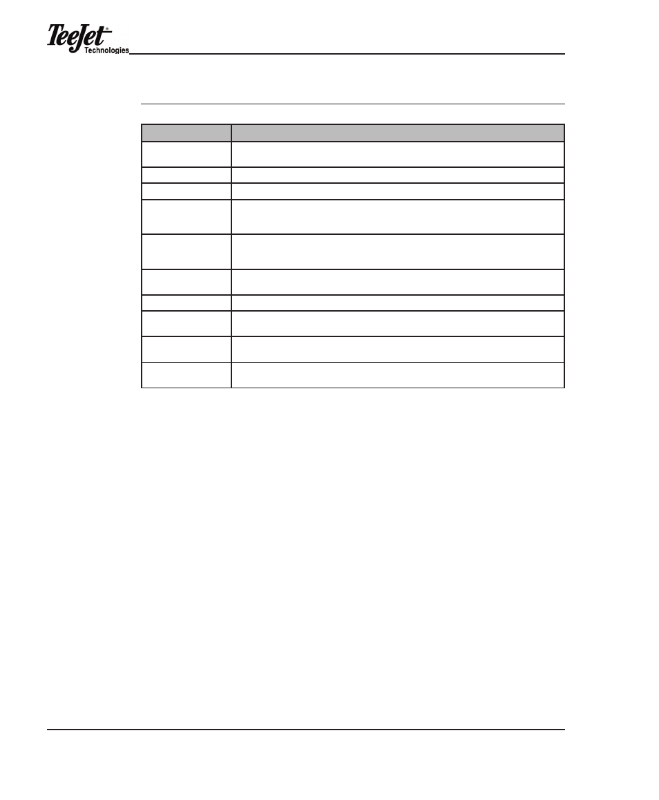
Table 2-5: Implement Setup Parameters
setting
description
implement width
distance between guidelines (typically vehicle swath or spread width used for guidance
purposed. width FoR guidaNCe oNLy!
Number of Swaths
defaults to 1. For each product applied there could be a separate swath.
Sections
the number of sections that comprise a swath.
Section 1 Switch
Section 2 Switch
Section 3 Switch...
indicates which boom switch controls section 1 of swath 1. if there are additional sections,
implement Setup will alternate between Switch and Boom width setup until all sections are
complete.
Boom 1 width
Boom 2 width
Boom 3 width...
the width of each boom section. if there are additional booms, implement Setup will alter-
nate between Switch and Boom width setup until all sections are complete.
offset direction y
the direction (along the center line of the vehicle) from the gPS antenna to the center of the
swath (FoRwaRd/BaCk).
offset distance y
distance from the gPS antenna along the vehicle center line to the swath.
offset direction X
the direction perpendicular (left or right) of the vehicle center line that the center of the
swath is offset.
offset distance X
the distance from the center of the vehicle to the swath. if the offset direction X was set to
NoNe, this screen will not appear.
Channel assignment
allows the assignment of channel to a swath or swaths. a swath can have a single channel
or all channels assigned.
NOTE: Swath Manager automatic boom section control can only be used with
single-Swath Implement configurations. Swath Manager also dictates that
the boom-to-switch assignment in Implement Setup is 1-1, 2-2, 3-3, etc.,
in numerical order from left to right beginning with Section 1. Any other
configuration is incompatible with Swath Manager.