Installation (cont.), Neutral resistor assembly, Installation of neutral resistor assembly – Rockwell Automation 7000A PowerFlex Medium Voltage Drive (A-Frame) - Classic Control User Manual
Page 52
2-12
Drive Installation
7000A-UM150F-EN-P – June 2013
7000 “A” Frame
Installation (cont.)
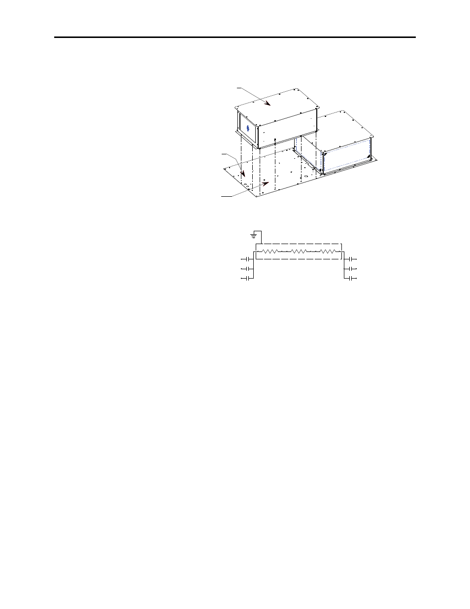
Neutral Resistor Assembly
Top Plate for Neutral
Resistor Housing
Ground Resistor
Hood here
Top Plate for Converter
and Common Mode
Choke Cabinet
900 mm Converter –
800 mm Common Mode Choke Cabinet
Neutral Resistor Assembly
Motor Filter
Capacitors
Line Filter
Capacitors
Refer to Electrical Drawings
to verify cable rating
to connect neutral
resistor assembly.
Attach ground
to top plate
Figure 2.7 – Hood Assembly for Neutral Resistor
Installation of Neutral Resistor Assembly
(Drives with Common Mode Chokes)
On top of the converter cabinet, a sheet metal enclosure containing
power resistors is to be installed.
1. Locate the resistor assembly on top of the cabinet as shown in
Figure 2.7.
2. Affix the assembly to the top plate using M6 thread forming
screws provided.
3. Remove the top plate of the resistor assembly to permit access to
the wiring connection points.
4. Connect the resistor wiring and per the electrical diagram
provided with the drive, a typical connection diagram is shown
in Figure 2.7. Ensure that the resistor wiring is routed through
the hole having a plastic bushing to protect the wire insulation.
The neutral resistor assembly housing has a ground connection
that is to be connected to the top plate of the drive.
5. Re-install the top plate of the neutral resistor housing.