Rockwell Automation 7000A PowerFlex Medium Voltage Drive (A-Frame) - Classic Control User Manual
Page 242
4-68
Commissioning
7000A-UM150F-EN-P – June 2013
7000 “A” Frame
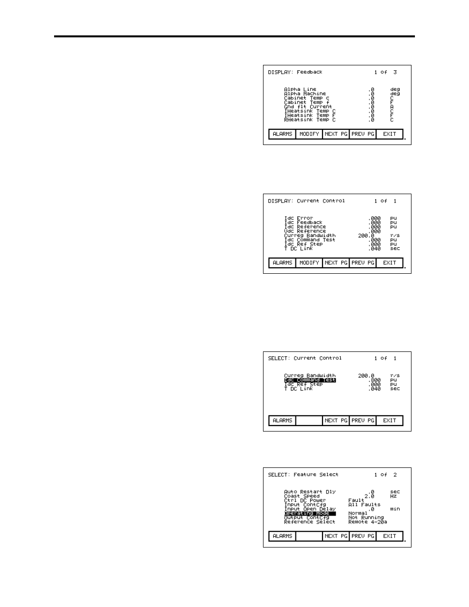
Press the start button and the drive should start running, pumping 0.1 pu (10%) of rated
current through the DC link. Alpha Line should be approximately 90°-92°.
We can also check the Idc Reference and
Feedback. Press EXIT [F10], and scroll back
down to Current Control and press Enter.
Idc reference should be at 0.100 pu and Idc
Feedback should be around that same number.
Ensure that Idc error stays around 0.
The Idc waveform can be observed from TP68 (IDCP) on the SCB-L. There are 2 IDCP test
points with TP68 being the unfiltered version. The test point should show 6 ripples per cycle
for a 6-pulse drive. The waveform should have an offset of 0.5V for each 0.1pu of Idc Test
Command. The waveform should also never have any of the low points between ripples go
to 0V. This would indicate a problem with the DC Link cabling. See the troubleshooting
section for sample waveforms.
Press MODIFY [F7], and increase Idc to .2
pu, and repeat the process. Go as high as 0.7
pu in .1 steps for 18P, and 0.3 pu in .1 steps
for PWM, verifying each level as you
increase the current. For PWMR, the Idc test
is limited to 0.3 Idc reference. If there is a
current meter somewhere on the input to the
transformer/drive, check the current to
ensure that it matches up with what you think
we are pumping.
When we are satisfied everything is OK,
bring the IDC current down in steps of .1 pu
to 0, and then stop the drive. Return to the
Feature Select parameter group and change
Operating Mode back to Normal.