Rockwell Automation 7000A PowerFlex Medium Voltage Drive (A-Frame) - Classic Control User Manual
Page 205
Commissioning 4-31
7000 “A” Frame
7000A-UM150F-EN-P – June 2013
SGCT Anode to Cathode Resistance
Performing an Anode to Cathode resistance test not only tests the
integrity of the SGCT but also the integrity of the sharing resistor.
An abnormal device resistance measurement will indicate either a
shorted device or damaged sharing resistor.
Using an ohmmeter, measure the anode to cathode resistance each
SGCT in the inverter bridge, looking for similar resistance values
across each device. Easy access from the anode to cathode is available
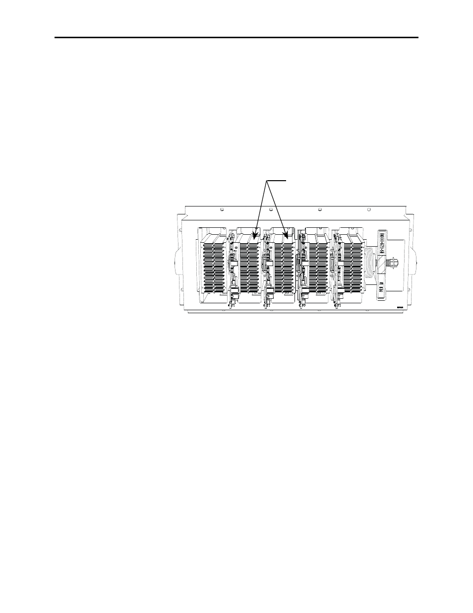
by going from heatsink to heatsink as shown in the diagram below:
Measure anode to cathode resistance
by testing from heatsink to heatsink.
Figure 4.4 – Anode to Cathode Resistance Test Points
An SGCT when not gated on is an open circuit. A healthy device
resistance value should be close to the value-sharing resistor,
however due to parallel resistances in the firing card, the resistance
value will be slightly lower.
Example: The resistance across the anode to cathode of a 400 amp
device may be 57 kΩ even though the sharing resistor is
80 kΩ.
A failure of an SGCT can be detected by measuring a lower than
normal resistance value; one device in the converter may read 15 kΩ
whereas the rest of the devices in the converter measured close to 60
kΩ. This indicates a partially shorted device. A fully shorted device
will read closer to 0 Ω and will be quickly identified. If the SGCT is
found to be out of tolerance, refer to Chapter 6 – Component
Definition and Maintenance for detailed instructions on how to
replace the SGCT assembly.