Rockwell Automation 7000A PowerFlex Medium Voltage Drive (A-Frame) - Classic Control User Manual
Page 461
Troubleshooting
7-23
7000 “A” Frame
7000A-UM150F-EN-P – June 2013
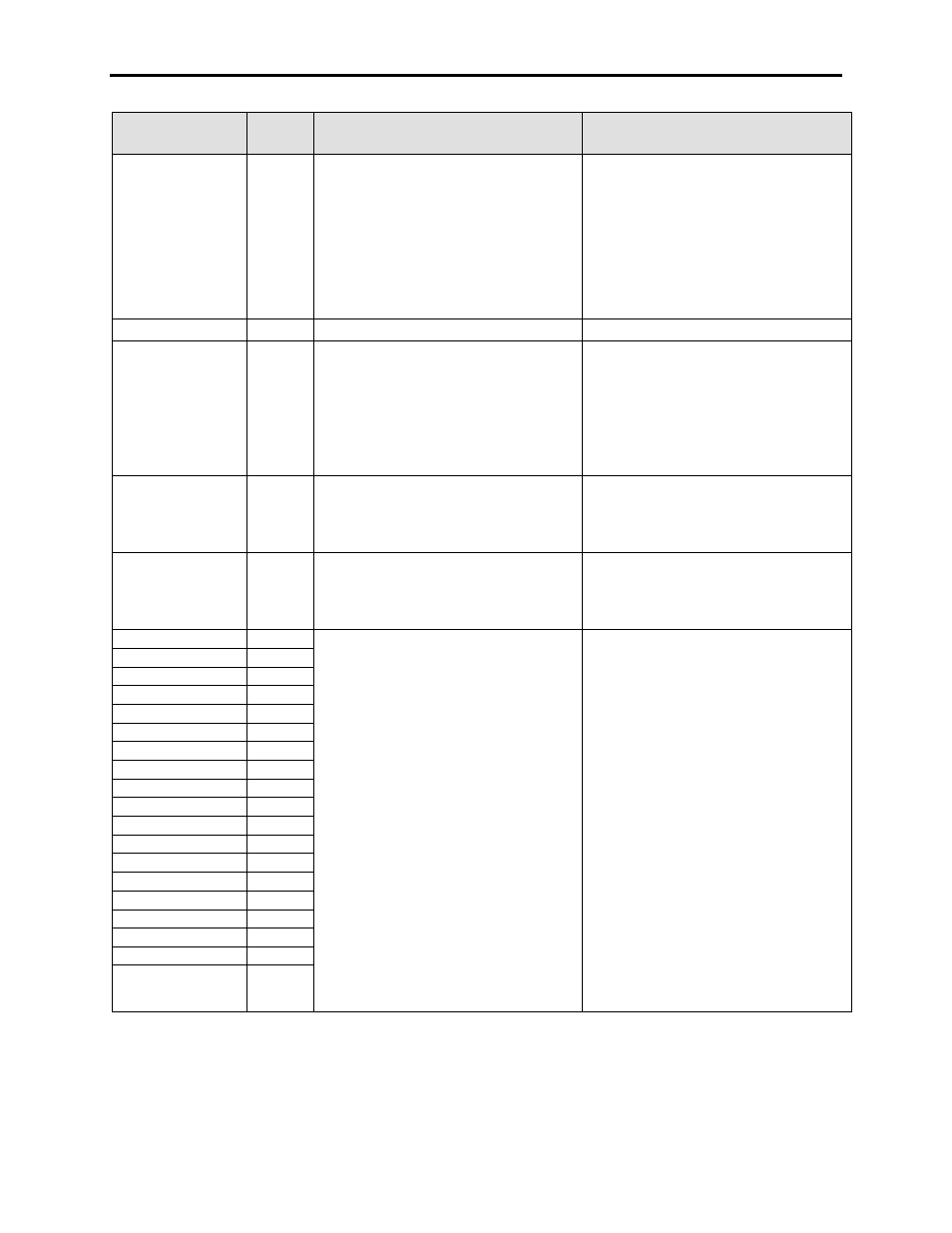
FAULT
MESSAGE
FAULT
CODE
DESCRIPTION
RECOMMENDED ACTIONS
Sync Xfer Failed
75
A Synchronous Transfer was not completed
in the time specified in Synchronous
Transfer Time (P230) and the drive has
faulted. This fault will only occur if the
parameter Sync Xfer Option (P419) is
configured as Enable Fault. If the
parameter is set as Enable Warn, the drive
will go back to last speed command and
issue a warning.
– Instability at Synchronous Speed - Check
for stability of the synchronous transfer
process/ speed regulator
– Load can not reach Synchronous Speed
– Check load conditions for torque limit
or low alpha line (low line voltage)
– Consult factory for review of
synchronous transfer parameters
Tach Loss F
42
Tach Loss fault
– Check the tach feedback
Temp Feedback Ls
(C-Frame only)
232
This fault occurs only if the drive is not
running. The drive has detected missing
temperature feedback from the cooling
system. A missing sensor can be
interpreted as either 0°C or over 100°C, and
both are unrealistic values, so it is
considered a Feedback Loss.
– Verify sensor is completely seated
properly on TFB.
– Measure sensor resistance.
– Verify Fiber Optics are properly seated
on TFB
– Verify the TFB has power
– Replace if necessary.
Terminal USART
241
CIB Hardware Fault
– CIB Hardware Problem
– Cycle control Power to the drive, and if
the problem still exists the board should
be replaced
XIO Interface
244
CIB Hardware Fault
– CIB Hardware Problem
– Cycle control Power to the drive, and if
the problem still exists the board should
be replaced
U1A Device Flt
117
INVERTER SGCT FAULT
This fault will only occur during the initial
contactor closure and the diagnostic
sequence after a start command. The
inverter monitors the state of the feedback
before a gate pulse is given, and monitors
the feedback after a gate pulse has been
sent. The SGCT has smart diagnostics, so
the feedback may indicate short before
firing, and if the pulse is received and the
device is really shorted, the diagnostic will
toggle the feedback to let you know the
problem is with the device, or the power
supply for that device.
The firmware now completes a diagnostics
sequence immediately after any drive reset,
with the goal of detecting faults before any
destructive action is taken from the next
action
– Complete a resistance check per the
instructions in the manual
– NOTE: SGCTs may not have completely
shorted, and still could read in the kΩ
range – Any devices with low suspect
readings should be changed
– Check the LED status of the SCGT gate
driver card for abnormal readings
– Complete a Gating Test mode check on
the devices
– Verify the associated 20V power supply
is powered and active
– Verify all the power connections to the
SCGT firing card are seated properly
U1B Device Flt
123
U1C Device Flt
480
U4A Device Flt
120
U4B Device Flt
126
U4C Device Flt
483
V3A Device Flt
119
V3B Device Flt
125
V3C Device Flt
482
V6A Device Flt
122
V6B Device Flt
128
V6C Device Flt
485
W2A Device Flt
118
W2B Device Flt
124
W2C Device Flt
481
W5A Device Flt
121
W5B Device Flt
127
W5C Device Flt
484