Rockwell Automation 7000A PowerFlex Medium Voltage Drive (A-Frame) - Classic Control User Manual
Page 399
Component Definition and Maintenance 6-95
7000 “A” Frame
7000A-UM150F-EN-P –June 2013
The standard drive comes with one XIO board, although additional boards
can be paralleled through the same type of CAN Link connection, from
XIO Link B (J5) on the first board to XIO Link A (J4) on the second
board, and so on. Specific applications may require the additional inputs
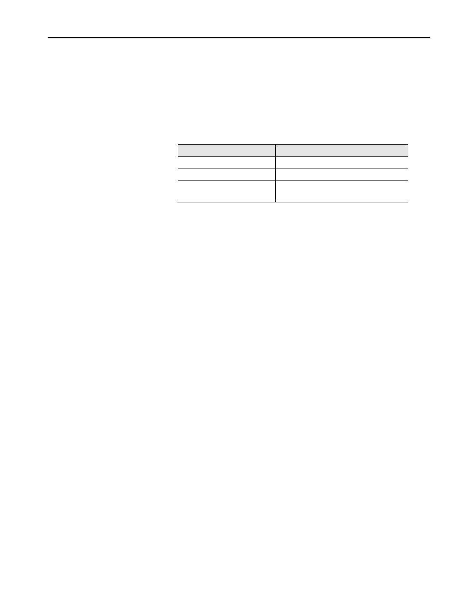
and outputs. U6 on the XIO board displays the XIO address. LED DI
indicates the status of the board. The following table illustrates the
possible states.
LED Status
Description
Solid Green
Communication to CIB OK
Solid Red
Board Failure
Alternate Flashing of Red and
Green
No Communication Available to CIB board
(Normal during boot-up or unprogrammed)
External Input/Output Board Replacement
To replace the External Input/Output Boards:
1. Ensure that all medium voltage and control voltage power to the drive
is isolated and locked out.
2. Note and Mark the location and orientation of all the plugs, cables,
and connectors into the XIO board. Use the electrical drawing as a
reference.
3. Using your static strap, disconnect all of the connections.
4. Remove the XIO board assembly from the low voltage control
cabinet. The XIO board mounts on a DIN rail, so a special
3-piece assembly is used to secure the board. The assembly does
not come with the new board, so the old board needs to be removed
from the assembly and the new board installed in its place.
5. Install the new XIO board assembly in the low voltage control
cabinet.
6. Reconnect all connections and verify the locations.
7. Apply Low Voltage power and complete a System Test and Medium
Voltage tests to ensure the new board functions properly.