Drive control boards (cont.) – Rockwell Automation 7000A PowerFlex Medium Voltage Drive (A-Frame) - Classic Control User Manual
Page 386
6-82
Component Definition and Maintenance
7000A-UM150F-EN-P –June 2013
7000 “A” Frame
Drive Control Boards (cont.)
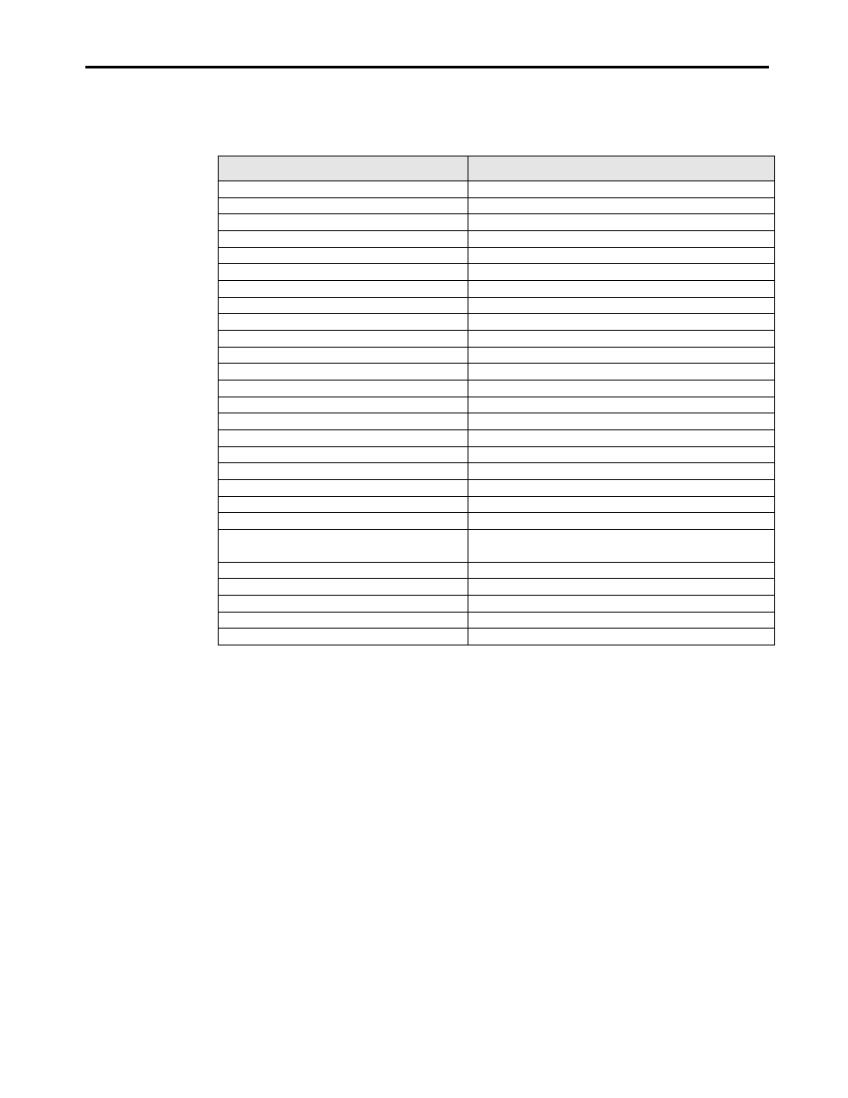
LED STATUS
CONDITION
Solid Green
Application Firmware Running
Flashing Green @ 0.25 Hz
Download Mode
Flashing Green @ 0.50 Hz
Download Mode – Currently being Programmed
Flashing Green @ 1.0 Hz
Ready
Flashing Green @ 2.0 Hz
Testing Flash Memory
1 Green Pulse
Waiting for Release upon Startup
2 Green Pulses
DCB-L – Waiting for DCB-M Status
3 Green Pulses
DCB-L – Waiting for CIB Status
10 Green Pulses
Tests Passed
Off
DCB in Test Mode
Solid Red
POST Failure – DSP
Flashing Red @ 0.25 Hz
Waiting for CIB
Flashing Red @ 0.50 Hz
Waiting for DCB
Flashing Red @ 1.0 Hz
Waiting for Adjacent Board
2 Red Pulses
POST failure - RAM
3 Red Pulses
POST failure – NVRAM
4 Red Pulses
POST failure – DPRAM
5 Red Pulses
POST failure – Application Flash
6 Red Pulses
POST failure – Text Flash
7 Red Pulses
POST failure – External DPRAM
8 Red Pulses
Failed FPGA Loading
9 Red Pulses
POST failure – USART – 1 Green Flash = Port 1
POST failure – USART – 2 Green Flashes = Port 2
10 Red Pulses
Returned from Application and Halted
11 Red Pulses
Programming Error - CRC
12 Red Pulses
Programming Error – Connection
13 Red Pulses
Programming Error – Feedback
14 Red Pulses
Programming Error – Overflow
There is also a healthy LED labeled D2 on each DCB. This LED is an
indication of several things, including a healthy watchdog between the
adjacent board, and healthy DC voltages. The light will go out if either of
the DC voltages (except the 5V) drops too low, or if the watchdog is
absent for 10 consecutive samples. The watchdog is annunciated every 1
ms. The DCB OK contact on the SCB operates in parallel to the D2 LED.
When D2 is on, DCB OK is closed.