Temperature sensing – Rockwell Automation 7000A PowerFlex Medium Voltage Drive (A-Frame) - Classic Control User Manual
Page 325
Component Definition and Maintenance 6-21
7000 “A” Frame
7000A-UM150F-EN-P –June 2013
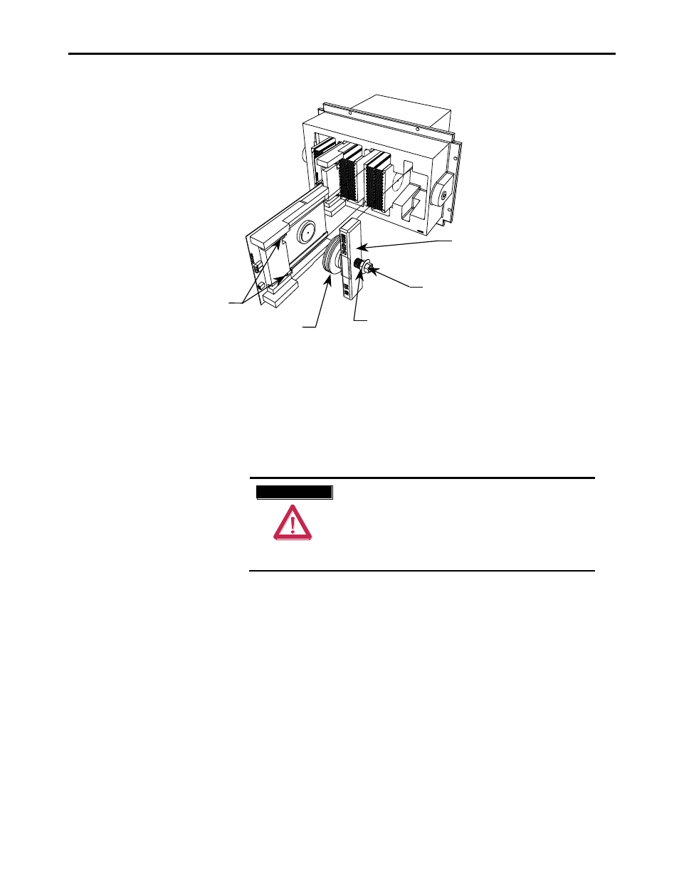
SGCT captive screws
Clamp head block
Disc springs
Inside nut used for loosening
and applying load to assembly
DO NOT ADJUST outside nut.
Figure 6.19 – Detail of the clamping assembly
Temperature Sensing
Thermal sensors are located on one heatsink in the rectifier and one
heatsink in the inverter. The thermal sensors are mounted on the heatsink
with the temperature feedback circuit board.
1. Ensure there is no power to the equipment.
A T T E N T I O N
A T T E N T I O N
To prevent electrical shock, ensure the main
power has been disconnected before working on
the drive. Verify that all circuits are voltage free
using a hot stick or appropriate voltage-
measuring device. Failure to do so may result in
injury or death.
2. To replace a thermal sensor, refer to Preface page P-2, regarding
electrostatic discharge.
3. The heatsink with the thermal sensor must be removed from the
PowerCage. Remove clamp load (refer to Figure 6.18).
4. Remove the device (SGCT or SCR) that is secured to the heatsink with
the thermal sensor. (Refer to Figure 6.14., 6.15, 6.16,
6.19
or
6.20
).
5. Disconnect the fiber optic cable to the temperature feedback board.
6. Remove two M8 screws holding the heatsink in place.
7. Remove the heatsink with the temperature feedback board from the
PowerCage.