Rockwell Automation 7000A PowerFlex Medium Voltage Drive (A-Frame) - Classic Control User Manual
Page 235
Commissioning 4-61
7000 “A” Frame
7000A-UM150F-EN-P – June 2013
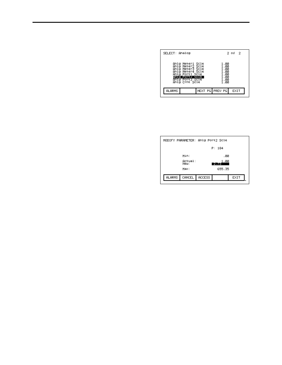
If you scroll down, you will reach the scaling
factors for the 4 Meter Port and the 3 CIB
Port outputs. All parameters are scaled to 0-
10V, with 0 representing the minimum value
given in Chapter 6 under Parameter
Descriptions, and 10V representing the
maximum value given in Chapter 6. These
Scaling parameters (i.e. Anlg Port2 Scle) can
be used to change the scaling.
Note: There are certain parameters whose minimum value is a negative number. In that
case, the minimum value of the parameter (-10V) is scaled to 0V output and the
maximum value is scaled to 10V output.
Highlight the appropriate Analog Scale
parameter and press Enter. You can enter
your new value, and then press Enter, and
EXIT (F10). Ensure you save to NVRAM
when you are finished.
The analog outputs from the customer interface boards are stated as 0
to 10 volts, but in actual fact their outputs are typically 0.025 to 9.8 or
9.9 V. This is due to the rails being loaded down by an attached
speed potentiometer or signal conditioner impedance. Incorporated
signal conditioners usually have 0 to 10-volt inputs and 4 to 20 mA
outputs. An additional error is incorporated in the signal conditioners,
so if they are calibrated for 0 to 10 volts input, there will not be
exactly 4 to 20 mA out.
It is now necessary to calibrate the external 4 to 20 mA signal
conditioners.
1. Set a digital multimeter to mA and place it in series with the
signal conditioners. If the output of the conditioner is terminated,
the meter can be used as a load.
2. Assign a parameter to the Analog Output port that we wish to
calibrate. This parameter should be one that we can change from
minimum to maximum for test purposes only. IDC Command
Test is a good example. See previous page on assigning an
output.