Rockwell Automation 7000A PowerFlex Medium Voltage Drive (A-Frame) - Classic Control User Manual
Page 446
7-8
Troubleshooting
7000A-UM150F-EN-P – June 2013
7000 “A” Frame
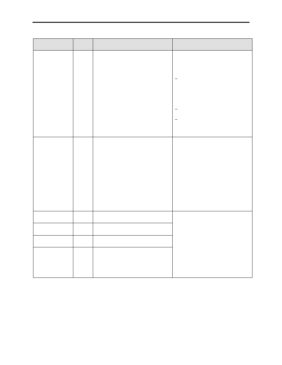
FAULT
MESSAGE
FAULT
CODE
DESCRIPTION
RECOMMENDED ACTIONS
DC/DC Fail
155
The last of the 5VDC or the 15VDC supplies
from the DC/DC power supply to the drive
control logic has failed, or any of the other
voltages that are non-redundant have failed.
This fault means that you will have no
voltage on a required output.
– Measure the input voltage to the DC/DC
power supply and verify it is at 56VDC
– Measure the output voltage and compare
to expected values listed in Chapter 4 of
the User‟s Manual
– Verify fault detection wiring is per the
drawings, and measure the voltage on the
trip signals back to the CIB. The 5VDC is
supplied from the CIB to the fault circuit,
and is pulled low on the power supply
when healthy.
– Verify the output from the alarm signal is
wired correctly.
– If 5V DC signal from CIB is not pulled low
when connected to the DC/DC power
supply, then the power supply is the
cause. Replace the power supply.
DPI Interface
243
This fault typically occurs when you have
the Communication Type (P147) set for
500k (DPI only), and you have a SCANPort
adapter connected to the CIB. SCANPort
operates at 125k, and the DPI can operate
at both speeds. This can also occur if the
SCANPort network attempts to access Port
5, which is internally assigned to DPI.
Note: „MOD A‟ LED on the CIB indicates a
healthy SCANPort Adapter when Green.
„MOD B‟ LED on the CIB indicates a healthy
DPI Adapter when Green.
– Ensure Communication Type is set for
125k for any drive with SCANPort
connections
– Ensure you are not using a SCANPort
splitter with Port 5 active as the drive
internally has assigned Port 5 to DPI,
and this conflict will create a fault
– Cycle power to ensure you
Communication Type change takes
effect
– The final cause could be a CIB Hardware
problem, and the board should be
replaced if the above actions are
unsuccessful
DI Contactor
18
The Drive Input Contactor has opened
without command from the PF7000 drive.
– The drive system needs to have
complete control over all contactors, so
investigation of the specific contactor
fault is required
– Verify contactor feedback
– Verify the control power circuit for the
contactor
– Check permissive string to the contactor
control relay (refer to drawing) -Check
contactor/breaker for physical
malfunction (auxiliaries)
– Check SCB inputs and outputs
DO Contactor
19
The Drive Output Contactor has opened
without command from the PF7000 drive.
OP Contactor
34
The system output contactor has opened
without command from the PF7000 drive.
BP Contactor
20
The Bypass Contactor has opened without
command from the PF7000 drive.