Rockwell Automation 7000A PowerFlex Medium Voltage Drive (A-Frame) - Classic Control User Manual
Page 361
Component Definition and Maintenance 6-57
7000 “A” Frame
7000A-UM150F-EN-P –June 2013
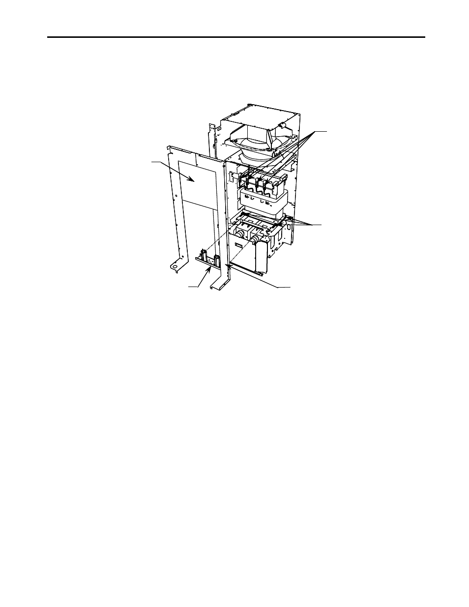
The DC link is heavy and has provision for lifting with forks of a lift
truck.
Step 3: Unfasten DC link leads and
remove terminal assembly.
Disconnect ground wire and
LV wires for thermal switch.
Step 4: Remove DC link hardware
and lift link out of front drive.
Step 1: Remove hardware and
DC link and fan barrier.
Step 2: Remove grounding
filter/network assembly.
Fan Barrier
Step 3: Unfasten DC link leads and
remove terminal assembly.
Disconnect ground wire and
LV wires for thermal switch.
Step 4: Remove DC link hardware
and lift link out of front drive.
Step 1: Remove hardware and
DC link and fan barrier.
Step 2: Remove grounding
filter/network assembly.
Fan Barrier
Figure 6.46 – DC link removal
Installation of the replacement DC link is performed in the reverse order
of its removal.
The installer must ensure that the flexible DC link leads are connected to
the appropriate terminal and routed so that electrical clearances are
maintained. You must also verify that the nameplate ratings are the same
or appropriate for the drive system. A different DC link will require
different parameter settings.
Thermal protection of the DC link reactor is provided by two normally
closed contacts wired to the I/O module. These contacts will open at
190°C and cause a fault/alarm message to be displayed.