Rockwell Automation 57C570 AutoMax PC3000 User Manual User Manual
Page 76
4Ć18
4.6.2
About Remote I/O System Grounding
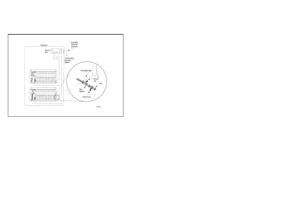
Figure 4.10 illustrates the recommended grounding configuration for
a remote I/O system. For more information about properly
grounding a remote I/O system, refer to the Rockwell Automation
Industrial Automation Wiring and Grounding Guidelines, publication
1770Ć4.1.
Figure 4.10 Ć Recommended Grounding Configuration for Remote I/O Systems
4.6.3
Recommended Switch Settings
Switches are used on remote I/O chassis and adapter devices for
defining:
D the I/O rack addressing method for the chassis, which defines
how much of a slot makes up a word in the I/O image table
D the state of the outputs in the chassis after a communication fault
D how the chassis can be reset
D the remote I/O link communication rate
D the I/O rack number and starting I/O group of the adapter device
Each chassis housing an adapter device has its own addressing
method (1Ćslot, 2Ćslot, 1/2Ćslot). The addressing method specified
for a chassis is independent from that chosen for other chassis in
the remote I/O system.