5 testing cable segments – Rockwell Automation 57C570 AutoMax PC3000 User Manual User Manual
Page 109
7Ć11
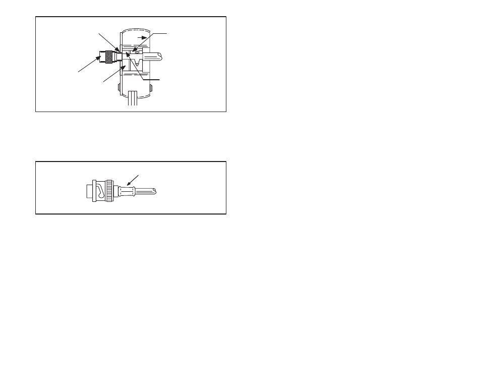
CABLE
SIDE
PLACE CONNECTOR
AND FERRULE,
ASSEMBLED ON
CABLE, IN UPPER
CRIMPING DIE
SHOULDER ON
CONNECTOR RESTS
AGAINST DIE
CONNECTOR
BRAID
CRIMP
LOCATE CONNECTOR
IN TOOL EXACTLY
AS SHOWN
Figure 7.18 Ć Place Connector Assembly in Tool
Step 13. Close the handles until the ratchet releases to complete
the crimp.
Step 14. Remove the crimped assembly from the crimping dies.
The connector is now attached to the coax cable, as
shown in figure 7.19.
CRIMPED FERRULE
Figure 7.19 Ć Connector Attached to RGĆ11/U Cable
7.5
Testing Cable Segments
Once a cable segment has been terminated with a connector on
each end, visually inspect the connector for loose connections,
nicked insulation, or loose strands from the braid that might cause a
poor connection or short. The center contact should be straight and
centered inside the connector dielectric. Be sure that the center
contact is inserted deep enough into the connector body. The tip of
the center contact should be about even with the end of the
connector dielectric. Be sure the ferrule is crimped tightly against
the body of the connector and that the shield braid wire does not
protrude from the ferrule. Check the cable's mechanical connections
by grasping the outer conductor connector in one hand and the
coax jacket in the other. Pull firmly. The connectors should hold.