Rockwell Automation 57C570 AutoMax PC3000 User Manual User Manual
Page 126
10Ć4
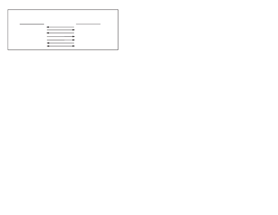
Programming Terminal End
9ĆPin Female Cable Connector
SIGNAL
PIN#
RECV
ă2
XMIT
ă3
CTS
ă8
RTS
ă7
DTRă4
DSRă6
COM
ă5
Reliance End
25ĆPin Male Cable Connector
PIN#
SIGNAL
ă2
XMIT
ă3
RECV
ă4
RTS
ă5
CTS
ă6
DSR
20
DTR
ă7
COM
Figure 10.3 Ć 9Ćpin to 25Ćpin Programming Cable
When making your own programming cable, follow these
recommendations:
D make sure that the cable is a 22Ćgauge multiĆconductor cable
D make sure the cable does not exceed 3 m (10 ft.)
D check for shorts and continuity with an ohmmeter
10.3.2
Setting the Communication Parameters
Before the programming device can communicate with the AutoMax
PC3000, you must make sure communications between the two
devices are set up correctly. To do this, follow these steps:
Step 1.
Run the AutoMax Programming Executive software.
Step 2.
From the Setup menu in the System Configurator, choose
Communication.
Step 3.
Choose Serial Port as the Communication Type.
Step 4.
In the Serial Port group box, choose:
D the serial port (Com 1 or Com 2) you have connected
to the AutoMax PC3000
D the baud rate that you want to use to communicate
with the AutoMax PC3000
Step 5.
To accept your changes, click OK.
10.4
Connecting a Modem to the AutoMax
PC3000 Via Port B of the Serial Card
You can connect to a remote AutoMax PC3000 by using modems.
Connect a modem to Programming Port B of the PC3000 Serial card
and then dial the modem from your site using a programming
device equipped with a modem.
The following sections assume you are using Hayes or
HayesĆcompatible modems and terminal emulation software such
as ProComm Plust.