Rockwell Automation 57C570 AutoMax PC3000 User Manual User Manual
Page 64
4Ć6
Choose from among these available addressing methods:
D 2Ćslot addressing
2 I/O chassis slots = 1 I/O group = 1 input
image word and 1 output image word =
16 input bits and 16 output bits.
D 1Ćslot addressing
1 I/O chassis slot = 1 I/O group = 1 input
image word and 1 output image word =
16 input bits and 16 output bits.
D 1/2Ćslot addressing
1/2 of an I/O chassis slot = 1 I/O group = 1 input
image word and 1 output image word =
16 input bits and 16 output bits.
x
x
x
x
x
x
x
x
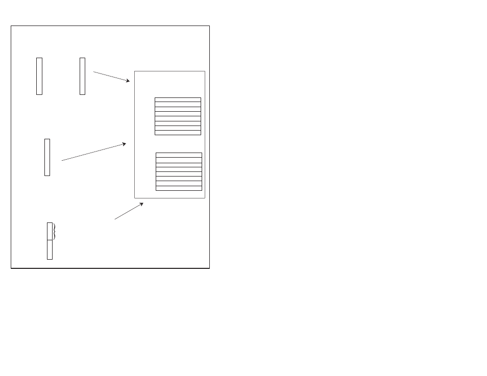
Output Image Table
Word #
Input Image Table
Word #
16 bits input
16 bits output
16 bits input and 16 bits output
16 bits input and 16 bits output
ЙЙЙЙЙЙ
ЙЙЙЙЙЙ
ЙЙЙЙЙЙ
ЙЙЙЙЙЙ
x
x
x
x
x
x
x
x
I/O Image Area
Rack X
Figure 4.3 Ć Available I/O Rack Addressing Methods
When you place your I/O modules in the I/O chassis slots, the
module's density determines how quickly I/O groups form. For
example, figures 4.4 and 4.5 show how 8Ć, 16Ć, and 32Ćpoint
modules utilize the scanner module's I/O image table when using
the 1Ćslot addressing method.