Rockwell Automation 57C570 AutoMax PC3000 User Manual User Manual
Page 107
7Ć9
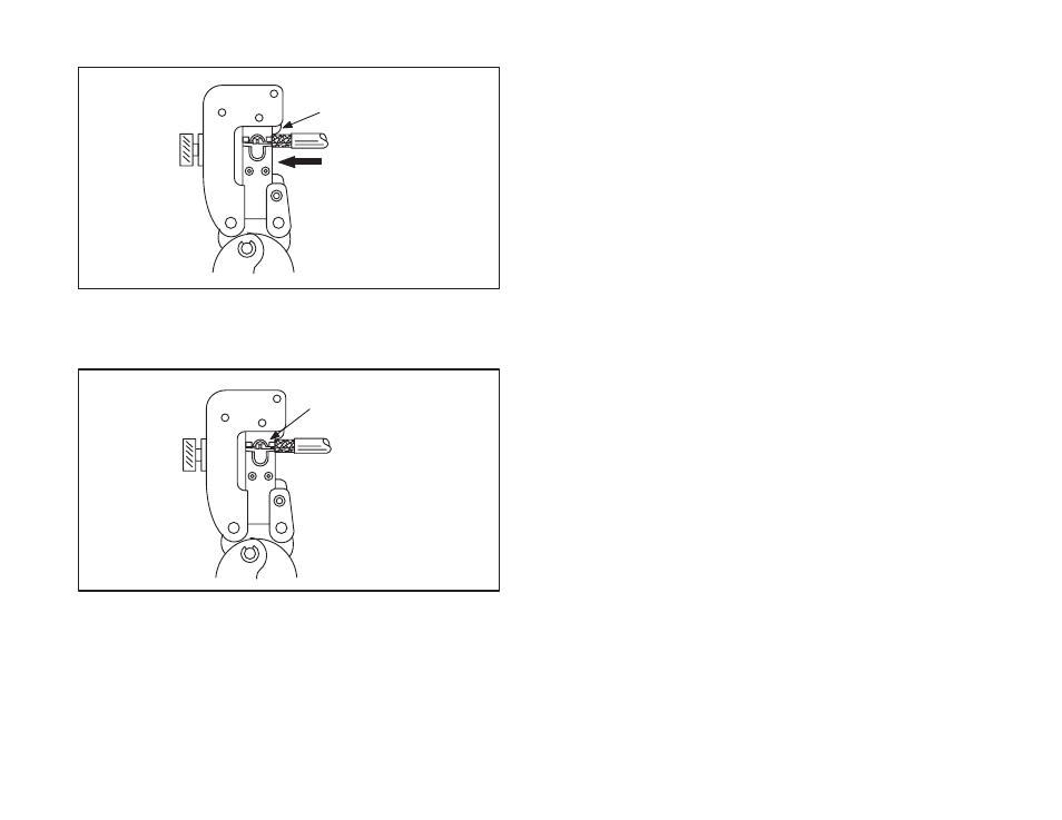
Step 5.
Push the cable in to hold the center contact against and
perpendicular to locator/stop as shown in figure 7.13.
DIELECTRIC BUTTS
AGAINST CENTER
CONTACT
PUSH CABLE IN
TO HOLD CENTER
CONTACT AGAINST
AND PERPENDICULAR
TO LOCATORĆSTOP
Figure 7.13 Ć Connector Installation Step 5 for RGĆ11/U Cable
Step 6.
Make sure that the raised area on the contact wire barrel
is located on the crimping die for proper termination as
shown in figure 7.14.
RAISED AREA ON CONTACT
WIRE BARREL MUST BE
LOCATED ON CRIMPING DIE
Figure 7.14 Ć Connector Installation Step 6 for RGĆ11/U Cable
Step 7.
Close the tool handles fully until the ratchet releases to
complete the crimp. Note that once the ratchet is
engaged, the handles cannot be opened until they have
been fully closed.
Step 8.
Remove the crimped contact.
Step 9.
Verify that the shield braid wire does not touch the center
contact. Refer to figure 7.15.