Rockwell Automation 57C570 AutoMax PC3000 User Manual User Manual
Page 55
3Ć17
StandĆAlone
FiberĆOptic
Transceiver
(continued)
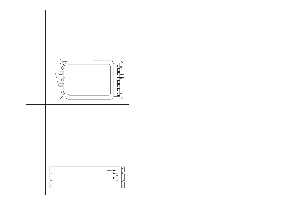
The green LEDs on either side of each connector indicate
the status of the receiver and transmitter and will flicker as
data is received and transmitted by the transceiver.
The opposite end of the transceiver contains a sixĆscrew
terminal block for operating power and signal connections.
The 24 V DC required for transceiver operation must be
provided externally. Note that terminal 6 (Ć24V) is internally
connected to the transceiver enclosure.
A jumper between terminals 3 and 4 is used to connect a
builtĆin 120 ohm terminating load between terminals 1 and
2. This jumper must be used on all StandĆAlone
Transceivers.
123
456
Receive LED
6Ćposition
Terminal Block
Transmit LED
FiberĆoptic
Ports
FiberĆOptic
Rack with
Power
Supply
The FiberĆOptic Rack and Power Supply (M/N 57C368) provide
the mechanical means of mounting and providing power for up
to 10 fiberĆoptic transceivers (M/N 57C367). Technical
specifications are listed in Appendix C.
The rack is a 19Ćinch, clear, anodized, aluminum enclosure with
a transparent plastic front panel. The rack contains a 115/230 V
AC power supply and 10 slots for transceivers. Each transceiver
receives operating power through plug connections at the
bottom of each slot in the rack. TransceiverĆtoĆtransceiver wiring
and connection to the fiberĆoptic link is done through openings
in the back of the rack.
The Power Supply consists of a 115/230 to 14 V AC transformer
connected to a standard IECĆstyle line cord. On the back of the
rack, there is a switch wired to the transformer to allow
switching the primary from 115 to 230 V AC. The faceplate of
the Power Supply contains an ON/OFF rocker switch and a 1.25
amp fuse. A builtĆin indicator in the ON/OFF switch will
illuminate to indicate the presence of power.
Fuse Holder
Power Status LED
Power Switch