Rockwell Automation 57C570 AutoMax PC3000 User Manual User Manual
Page 117
8Ć5
1
2
3
4
DATA Ć VIOLET WIRE
DATA Ć BLACK WIRE
NO CONNECTION
NO CONNECTION
ADAPTER
TERMINAL
CONNECTION
Figure 8.4 Ć RackĆMounted Transceiver Terminal Block Connections
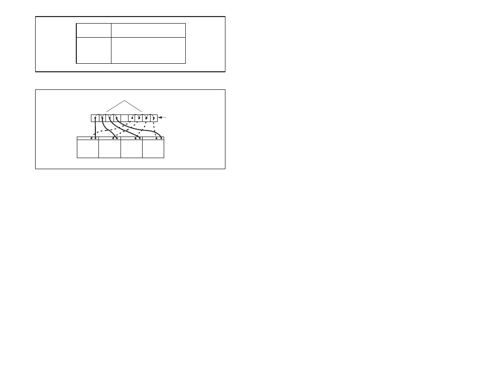
Jumper
21
21
21
21
Rack Containing Four Transceivers
Terminal Strip
Figure 8.5 Ć Connecting RackĆMounted Transceivers to a Terminal Strip
Step 5.
Connect each transceiver to the fiberĆoptic network using
the guidelines provided in section 8.5.
Step 6.
Verify that the external power supply is turned off.
Connect the power cord to a 115 or 230 V AC external
power supply. Note that the rack frame is grounded
directly through the ground pin of the line cord.
Step 7.
Use the rocker switch on the front of the Power Supply to
turn power ON to the rack. A builtĆin indicator in the
switch will illuminate signifying the presence of power.
Step 8.
Secure each transceiver with the captive screws on the
faceplate of the module. Attach the transparent plastic
front panel.