Rockwell Automation 57C570 AutoMax PC3000 User Manual User Manual
Page 130
11Ć2
3 2
1
3 2
1
3 2
1
E1
E2
E1
E2
1
1
3 2
1
20837ĆM
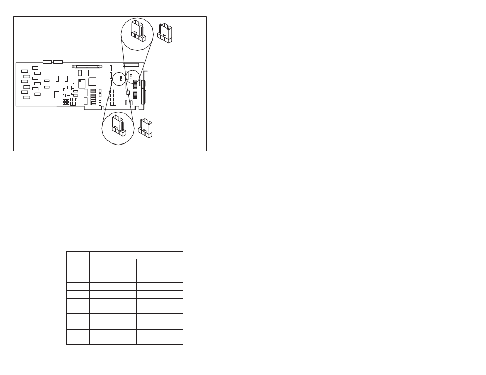
Serial Port A
Set for RSĆ422
Serial Port A
Set for RSĆ232
(default)
Serial Port A
Set for RSĆ232
(default)
Serial Port A
Set for RSĆ422
Figure 11.1 Ć Configuring Port A
Note: Pin 1 of jumpers E1 and E2 has a square pad mounted on the
back of the board.
11.1.2
Using the Correct Cable
Table 11.1 lists the pin assignments for Port A. The cable you connect
to Port A should have a 9Ćpin male connector that is properly wired.
When you are using the RSĆ422 protocol, do not use hardware
handshaking because the CTS, DTR, and DSR signals are not
available. When you are using hardware handshaking with the
RSĆ232 protocol, you must supply an external power supply
(5Ć12 V @2mA) connected to pin 6.
Table 11.1 Ć Pin Assignments for the AutoMax PC3000 Serial Card's Port A
БББ
БББ
БББББББББББ
БББББББББББ
Protocol
БББ
БББ
ББББББ
ББББББ
RSĆ232
ББББББ
ББББББ
RSĆ422
БББ
БББ
Pin
ББББББ
ББББББ
Assignment:
ББББББ
ББББББ
Assignment:
БББ
1
ББББББ
Not used
ББББББ
TXD (-).Out
БББ
БББ
2
ББББББ
ББББББ
RXD.In
ББББББ
ББББББ
RXD (+).In
БББ
БББ
3
ББББББ
ББББББ
TXD.Out
ББББББ
ББББББ
TXD (+).Out
БББ
БББ
4
ББББББ
ББББББ
DTR.Out
ББББББ
ББББББ
Not Used
БББ
БББ
5
ББББББ
ББББББ
SIGNAL.Gnd
ББББББ
ББББББ
SIGNAL.Gnd
БББ
БББ
6
ББББББ
ББББББ
DSR.In
ББББББ
ББББББ
Not Used
БББ
7
ББББББ
RTS.Out
ББББББ
Not Used
БББ
БББ
8
ББББББ
ББББББ
CTS.In
ББББББ
ББББББ
Not Used
БББ
БББ
9
ББББББ
ББББББ
Not Used
ББББББ
ББББББ
RXD (-).In