Rockwell Automation 57C570 AutoMax PC3000 User Manual User Manual
Page 108
7Ć10
SUPPORT
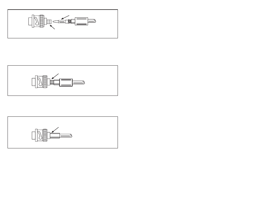
SLEEVE
OF CONNECTOR
CRIMPED CONTACT
Figure 7.15 Ć Connector Installation Step 9 for RGĆ11/U Cable
Step 10. Insert the crimped center contact into the connector body
until the cable dielectric butts against the dielectric inside
the connector body. The flared braid will then fit around
the support sleeve of the connector body, as shown in
figure 7.16.
BRAID OVER CONNECTOR
SUPPORT SLEEVE
Figure 7.16 Ć Connector Installation Step 10 for RGĆ11/U Cable
Step 11. Slide the ferrule forward over the shield braid wire and the
support sleeve until the ferrule butts against the shoulder
on the connector body, as shown in figure 7.17.
FERRULE SLID FORWARD
OVER BRAID AND SUPPORT
SLEEVE
Figure 7.17 Ć Connector Installation Step 11 for RGĆ11/U Cable
Step 12. Place the connector assembly in tool as shown in figure
7.18. Make sure that the ferrule assembled on the cable is
on the upper crimping die and that the shoulder on the
connector rests against the die, as shown.