0 - connecting an allen-bradley remote i/o link, 0 connecting an allenćbradley remote i/o link – Rockwell Automation 57C570 AutoMax PC3000 User Manual User Manual
Page 121
9Ć1
9.0 CONNECTING AN
ALLENĆBRADLEY REMOTE
I/O LINK
If you are using the AutoMax PC3000 Processor card to control
AllenĆBradley remote I/O, you must connect the remote I/O link.
For informtion about:
See this section:
Connecting the Remote I/O Link to
the Processor Card
9.1
What to Do Next
9.2
9.1
Connecting the Remote I/O Link to the
PC3000 Processor Card
Once the PC3000 Processor card is properly seated and secured in
the chassis, connect the remote I/O link.
If the Processor card is an end device on the remote I/O link, you
must install an appropriatelyĆsized terminating resistor while wiring
the remote I/O cable to the Phoenix connector. The resistor prevents
the signal from being reflected from the ends of the cable. A resistor
must be installed at each end of the link. You should have
determined the resistor size for the remote I/O link in section 4.3.2.
Both resistors used to terminate the link must be sized the same.
Also, make sure that the leads are short. Leads that are too long can
cause noise reflection on the link.
To connect the remote I/O link, follow these steps:
Step 1.
Locate a proper length of Belden 9463 cable.
Step 2.
Strip off enough of the cable jacket and insulation to
expose the wire inside each of the three segments.
Step 3.
Locate a Phoenix connector. This connector is shipped
installed on the Remote I/O port on the Processor card.
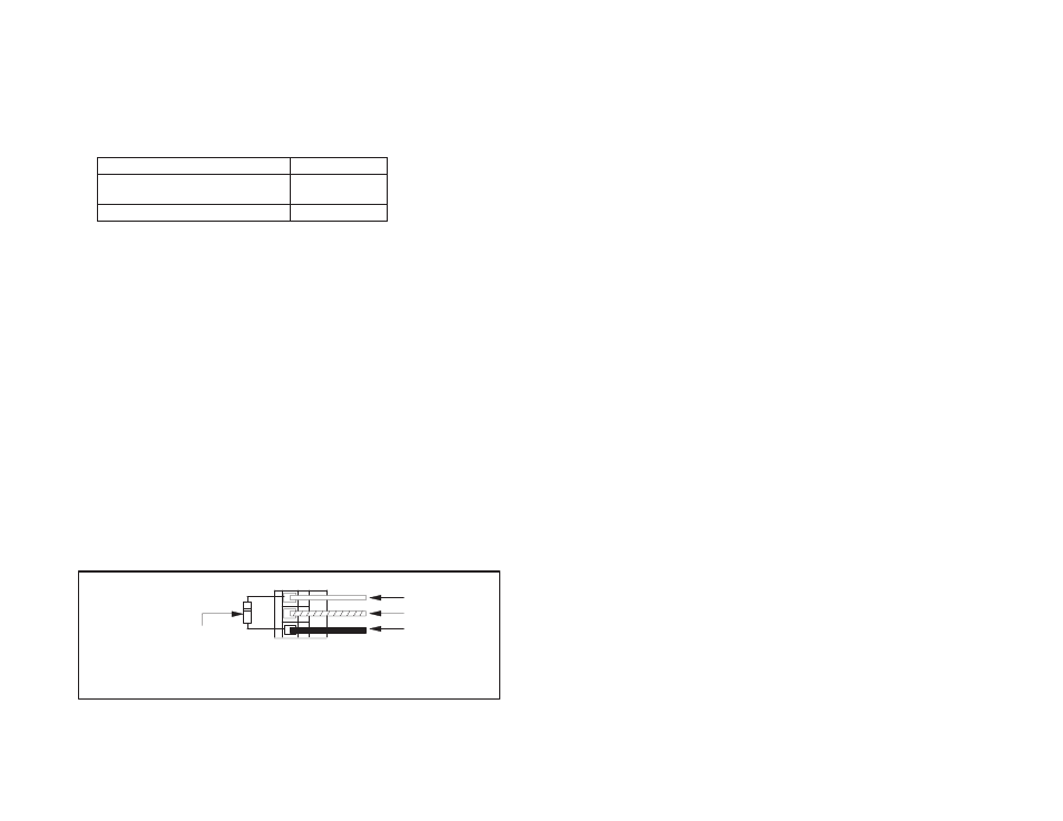
Step 4.
Connect the signal conductors and shield drain wire of
the twinaxial cable onto the connector's terminals as
shown in figure 9.1.
If the Processor card is an
end device, install an
appropriatelyĆsized
terminating resistor.
Clear (line 1)
Shield (Sh)
Blue (line 2)
Phoenix Connector
(oriented as if you are looking at the card as
it faces you with the LEDs upward)
Figure 9.1 ĆConnecting the Twinaxial Cable Segments onto the Phoenix
Connector