Rockwell Automation 57C570 AutoMax PC3000 User Manual User Manual
Page 276
GĆ4
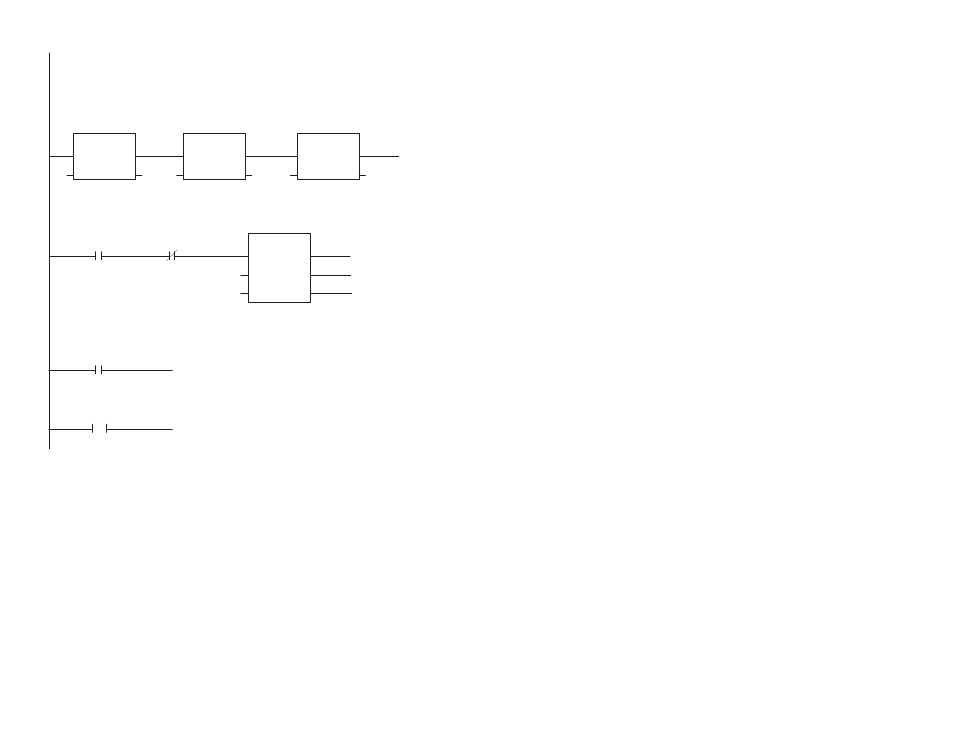
Ladder Language Program Example
1
1543
EN
ENO
In
Out
MOVE
Out=In
BT1_DEST
0
EN
ENO
In
Out
MOVE
Out=In
BT1_UPDATE 1
EN
ENO
In
Out
MOVE
Out=In
BT1_LENGTH
2
time
EN
ENO
Name/Elapsed
Q
TON
Time Base= 0.01 sec
BT1_XFR_INITIATE
BT1_XFR_COMP
BT1_XFR_ERR
TPreset
T
20
3
bt_error
(JMP)
4
bt_error
error_routine
( )
LBL
This rung examines the blockĆtransfer error bits and waits 0.2 s before initiating
the blockĆtransfer.
This rung examines the blockĆtransfer error bit. If the bit is on, the JMP coil
jumps to Rung 4 which would be an error routine.
As in the BASIC program, this rung sets up a nonĆcontinuous blockĆtransfer
write request of one word to a blockĆtransfer module in Rack 7, Group 3, and
Slot 0. In the first MOVE instruction, the decimal value of 1543 equals the hexaĆ
decimal value of 607H. This instruction specifies the target module's location
and a write request. The second MOVE instruction specifies a nonĆcontinuous
blockĆtransfer request. The third MOVE instruction specifies the length of the
request.
( )
BT1_XFR_COMP
How Physical I/O Translates into
Logical Remote I/O Groups
This section illustrates how I/O is laid out to form logical I/O groups in the
AllenĆBradley addressing schemes. The examples present 1Ćslot, 2Ćslot, and
1/2Ćslot addressing schemes using various I/O module densities. These
examples also show how the I/O groups are mapped into the PC3000 scanner's
I/O image table.
While these examples are based on the SLC 500 chassis, the concept applies to
other remote I/O platforms, such as 1771, Flex I/O, and Block I/O.