Rockwell Automation 57C570 AutoMax PC3000 User Manual User Manual
Page 66
4Ć8
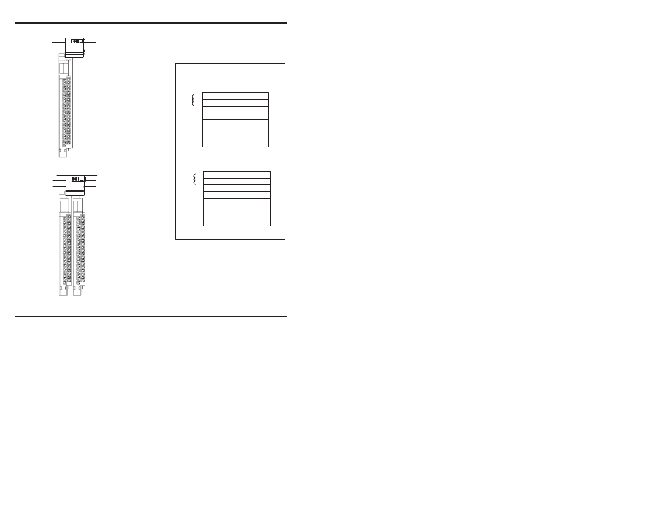
1Ćslot addressing (1 I/O chassis slot = 1 I/O
group = 1 input image word and 1 output
image word = 16 input bits and 16 output bits.)
0
1
2
3
4
5
6
7
Output Image Table
Word #
0
1
2
3
4
5
6
7
Input Image Table
Word #
00
15
bits
00
15
bits
ЙЙЙЙЙЙ
ЙЙЙЙЙЙ
Group 0
Group 1
32Ćpoint
output module
32Ćpoint
input module
ЙЙЙЙЙЙ
ЙЙЙЙЙЙ
ЙЙЙЙЙЙ
ЙЙЙЙЙЙ
32Ćpoint I/O modules use the
entire word of their I/O group
and borrow the entire word of
the next I/O group. See ➀.
Since the module is in I/O
group 0 and the inputs for I/O
group 0 and I/O group 1 are
used, you must:
•
install an output module in
I/O group 1
•
or leave the slot empty
Group 0
32Ćpoint
input module
Since the input image table for I/O group 1 is unavailable
because it is being used by the input module of I/O group
0, installing a 32Ćpoint output module makes use of the
output image table of I/O groups 0 and 1. See ➁.
You can also install 8Ć or 16Ćpoint output modules. But you
cannot install another input module since all the input
image space for I/O groups 0 and 1 are used by the input
module of I/O group 0.
0 1
0 1
I/O Image Area
Rack X
➀
➁
Figure 4.5 Ć Addressing Example Using 32Ćpoint I/O Modules
When planning your system design, consider the densities of the I/O
modules you are using and choose an addressing method that most
efficiently uses the I/O image area. See Figure 4.6.