3 designing a remote i/o link – Rockwell Automation 57C570 AutoMax PC3000 User Manual User Manual
Page 69
4Ć11
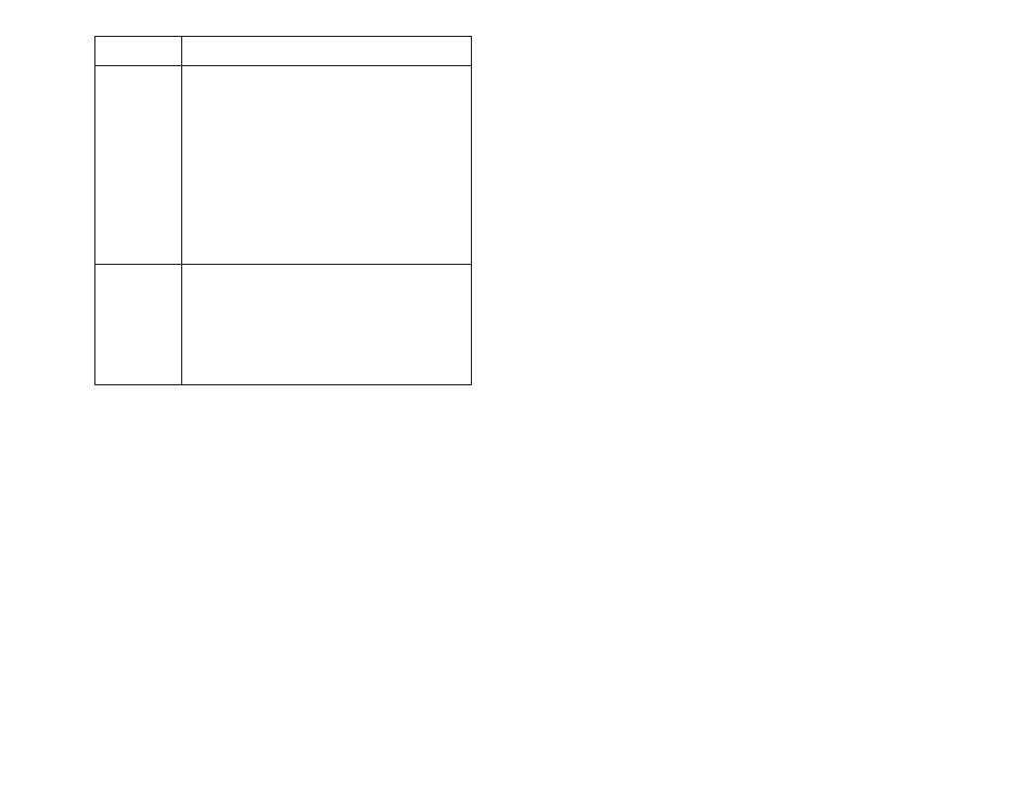
Addressing
Method
Guidelines
1Ćslot
D One I/O module slot = 1 group
D Each physical slot in the chassis corresponds to one
word (16 bits) in the input image table and one word (16
bits) in the output image table.
D When you use 32Ćpoint I/O modules, you must install as
a pair an input module and an output module in an
even/odd pair of adjacent I/O groups; if you use an input
module in slot 0, you must use an output module in slot
1 (or it must be empty). This configuration gives you the
maximum use of a rack's I/O image table.
D Use any mix of 8Ć and 16Ćpoint I/O modules, blockĆtranĆ
sfer, or intelligent modules in a single I/O chassis. Using
8Ćpoint modules results in fewer total I/O.
D Assign one I/O rack number to eight I/O groups.
1/2Ćslot
D One half of an I/O module slot = 1 group
D Each physical slot in the chassis corresponds to two
words (32 bits) in the input image table and two words
(32 bits) in the output image table.
D Use any mix of 8Ć, 16Ć, and 32Ćpoint I/O or blockĆtransfer
and intelligent modules. Using 8Ćpoint and 16Ćpoint I/O
modules results in fewer total I/O.
D Assign one I/O rack number to eight I/O groups.
4.3
Designing a Remote I/O Link
Use Belden 9463 (AllenĆBradley cable 1770ĆCD) cable for the
remote I/O network.
To design a remote I/O link you must:
D choose a data communication rate
D determine the cable lengths and terminating resistors you need