Rockwell Automation 57C570 AutoMax PC3000 User Manual User Manual
Page 67
4Ć9
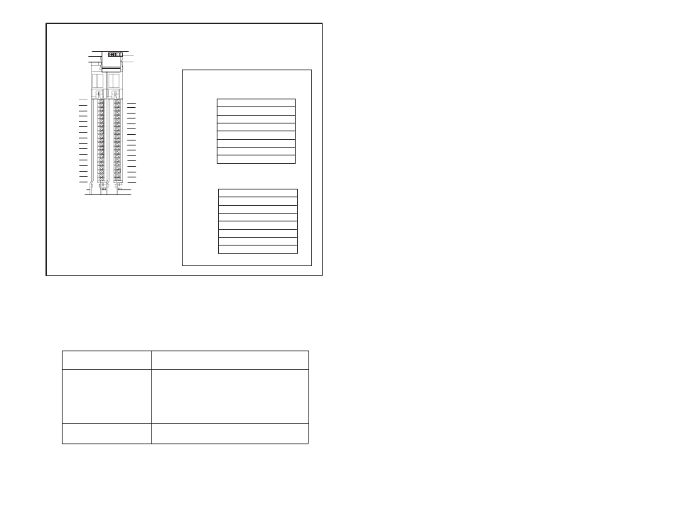
2Ćslot addressing (2 I/O chassis slot = 1 I/O
group = 1 input image word and 1 output
image word = 16 input bits and 16 output bits.)
0
1
2
3
4
5
6
7
Output Image Table
Word #
0
1
2
3
4
5
6
7
Input Image Table
Word #
ЙЙЙЙЙЙЙ
ЙЙЙЙЙЙЙ
I/O Image Area
Rack x
00
15
bits
00
15
bits
Group 0
ЙЙЙЙЙЙЙ
ЙЙЙЙЙЙЙ
16Ćpoint I/O modules occupy 16 bits,
an entire word, in the image table.
Installing as a pair a 16Ćpoint input
module and a 16Ćpoint output module
efficiently uses the image table.
00
01
02
03
04
05
06
07
10
11
12
13
14
15
16
17
00
01
02
03
04
05
06
07
10
11
12
13
14
15
16
17
Input
Terminals
Output
Terminals
NOTE: I/O terminals and racks are
numbered in octal.
Figure 4.6 Ć An Example of Efficient I/O Image Table Use
4.2.3
Addressing BlockĆTransfer Modules
BlockĆtransfer modules occupy 8 bits in the PC3000's I/O image
table. Since all blockĆtransfer modules are bidirectional, they cannot
be used to complement either input or output modules.
To address a module
occupying:
Use the:
one I/O chassis slot
assigned I/O rack and I/O group number of the
slot in which the module resides and 0 for the I/O
group slot number
When using 1/2Ćslot addressing, use the
assigned rack number, the lowest group
number, and 0 for the I/O group slot number.
two I/O chassis slots
assigned rack number, the lowest I/O group
number, and 0 for the I/O group slot number